


ICE·49
FUNCTIONAL DESCRIPTION
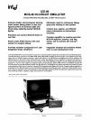
Debug Capability Inside User System
The
ICE-49
module provides the user with the ability
to
debug a full prototype
or
production system wi.thout
introduCing extraneous hardware
or
software test tools.
The module connects to the user system through the
socket provided for the
MCS-48 device in the user
system.
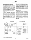
Intellec memory is used for the execution of the
ICE-49 software. The Intellec console and file handling
capabilities provide the designer with the ability to com·
municate
with
the ICE-49 module and display informa·
tion on the operation of the prototype system. The
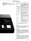
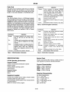
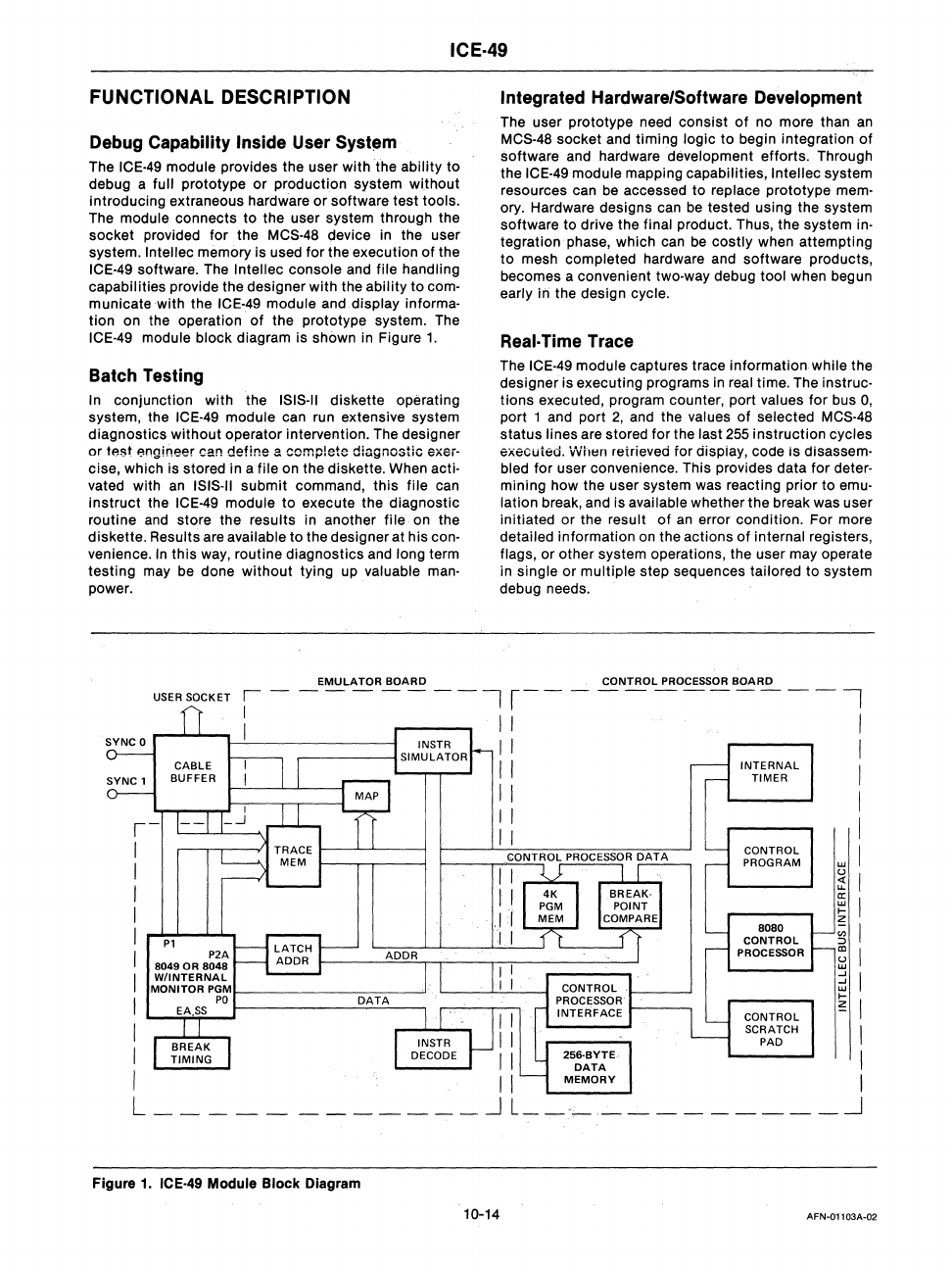
ICE-49 module block diagram is shown in Figure
1.
Batch Testing
In conjunction with the ISIS·II diskette operating
system, the
ICE-49 module can run extensive system
diagnostics without operator intervention. The designer
or
test engineer can define a comp!ete diagnostic
eX6i-
cise, which is stored in a file
on
the diskette. When
actio
vated with
an
ISIS·II submit command, this file can
instruct
the ICE-49 module
to
execute the diagnostic
routine and store the
results in another file
on
the
diskette.
Results are available
to
the designer at his con·
venience.
In
this
way, routine diagnostics and long term
testing may be done without tying up
valuable man·
power.
EMULATOR
BOARD
Integrated Hardware/Software Development
The user prototype need consist
of
no more than
an
MCS-48 socket and timing logic
to
begin integration
of
software and hardware development efforts. Through
the
ICE-49 module mapping capabilities, Intellec system
resources can
be
accessed
to
replace prototype
memo
ory. Hardware designs can
be
tested using the system
software to drive the
final product. Thus, the system in·
tegration phase, which can
be
costly
when attemptin.g
to
mesh completed hardware and software products,
becomes a convenient
two·way debug tool when begun
early in the design cycle.
Real· Time Trace
The ICE-49 module captures trace information while the
designer is executing programs
in
real time. The instruc·
tions executed, program counter, port values
for
bus
0,
port 1 and port
2,
and the values
of
selected MCS-48
status lines are stored for the last
255
instruction cycles
executed. When reirieved for dispiay, code is disassem·
bled
for user convenience. This provides data
for
deter·
mining how the user system was reacting prior to emu·
lation
break, and is available whether the break was user
initiated
or
the result of
an
error condition. For more
detailed information
on
the actions
of
internal registers,
flags,
or
other system operations, the user may operate
in
single or multiple step sequences tailored to system
debug needs.
CONTROL
PROCESSOR
BOARD
USER SOCKET I
I
-------11------------1
SYNC
0
r....l.....I....I-JI-------I
SYNC 1
CABLE
BUFFER
I-
I
I
I
I
I
I
I
I
I
I
I
P1
P2A
8049
OR
8048
WIINTERNAL
MONITOR
P~~I-
______
=,:;:-:-_---"
II
I
I I I
I I
INTERNAL
I
TIMER
II
I
I I I
I I
CONTROL
I
f-----,--=-::::.:-:..:., P
ROG
R
AM
UJ
8080
CONTROL
PROCESSOR
CONTROL
SCRATCH
PAD
~
!
~
I
z
~
I
~
I
~
1
!2
I
I
I
II I
L
__
_
_
______
~
L
__
·
__________
~
Figure
1.
ICE-49 Module Block Diagram
10-14
AFN-01103A-02