


SINGLE
COMPONENT
SYSTEM
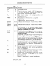
2.9.1
T1
Input
The
8021
T1
input
line can be used
as
an
input
for
the
following
functions:
• Event
Counter
(external input)
• Test
input
for
branch instructions
• Zero voltage crossing detection
The operation
of
T1
as
an
input
to the Event
Counter
is described in the Timer/Event
Counter
section. When used
as
a test input,
the
JT1
and JNT1
instructions
test
for
1 and
o levels, respectively.
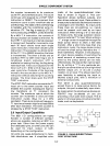
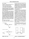
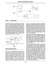
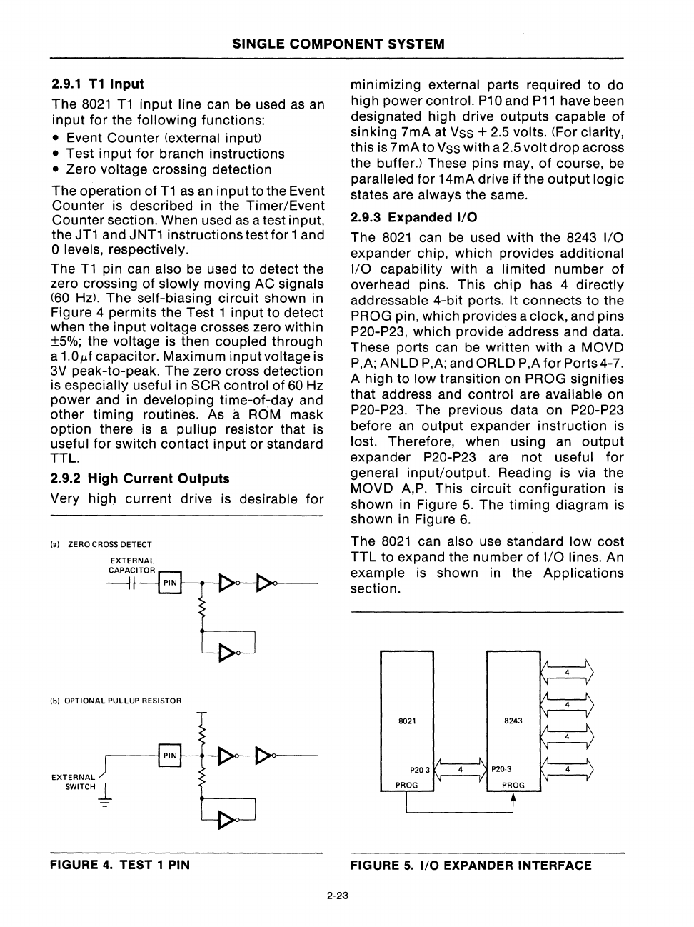
The
T1
pin can also be used to detect the
zero crossing
of
slowly
moving AC signals
(60
Hz)' The self-biasing
circuit
shown in
Figure 4 permits the Test 1
input
to detect
when the
input
voltage crosses zero
within
±5%; the voltage is then coupled
through
a
1.01-lf
capacitor. Maximum input voltage is
3V
peak-to-peak.
The
zero cross detection
is
especially useful in SCR control of
60
Hz
power and in
developing
time-of~day
and
other
timing
routines. As a ROM mask
option
there is a
pullup
resistor that is
useful
for
switch
contact
input
or
standard
TTL.
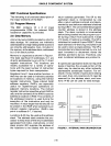
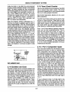
2.9.2 High Current Outputs
Very
hig~
current drive is desirable
for
(0) ZERO CROSS OETECT
EXTERNAL
Ibl
OPTIONAL
PULLUP
RESISTOR
EXTERNAL
SWITCH
~
FIGURE
4.
TEST 1 PIN
2-23
minimizing external parts required
to
do
high power control.
P10
and
P11
have been
designated high drive
outputs
capable
of
sinking 7mA at Vss +
2.5
volts. (For clarity,
this is 7mA to Vss with a 2.5
volt
drop
across
the buffer.) These pins may,
of
course, be
paralleled
for
14mA drive if the
output
logic
states are always the same.
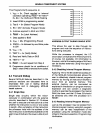
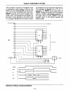
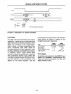
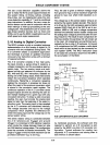
2.9.3 Expanded I/O
The
8021
can be used with the 8243
I/O
expander chip, which provides additional
I/O
capability with a limited
number
of
overhead pins. This
chip
has 4
directly
addressable 4-bit ports. It connects
to
the
PROG pin, which provides a clock, and pins
P20-P23, which provide address and data.
These ports can be written with a MOVD
P,A; ANLD P,A; and
ORlD
P,A
forPorts4-7.
A high to low transition on PROG signifies
that
address and control are available on
P20-P23. The previous data on P20-P23
before an
output
expander
instruction
is
lost. Therefore, when using an
output
expander P20-P23 are
not
useful
for
general
input/output.
Reading is via the
MOVD A,P. This
circuit
configuration
is
shown in Figure
5.
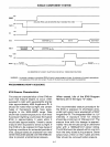
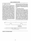
The
timing
diagram is
shown in Figure
6.
The
8021
can also use standard
low
cost
TTL
to expand the
number
of
I/O
lines. An
example is shown in the Applications
section.
FIGURE
5.
I/O
EXPANDER INTERFACE