8279/8279·5
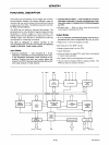
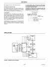
The
command
is then decoded and
the
appropriate
function
is
set. The
timing
control
contains
the
basic
timing
counter
chain. The first
counter
is a + N prescaler
that
can be
programmed
to
yield
an
internal
frequency
of
100 kHz
which
gives a
5.1
ms
keyboard scan
time
and
a
10.3
ms
debounce
time.
The
other
counters
divide
down
the
basic
internal
frequency
to
provide
the
proper
key scan, row scan, keyboard
matrix
scan, and
display
scan
times.
Scan Counter
The scan
counter
has
two
modes. In the encoded mode.
the
counter
provides a binary
count
that must be
externally
decoded to provide the scan lines
for
the
keyboard
and display. In the decoded mode. the scan
counter
decodes the least
significant
2 bits and provides a
decoded
1
of
4 scan. Note than when the keyboard is in
decoded
scan, so is the display. This means
that
only
the
first 4 characters in the Display RAM are displayed.
In
the
encoded mode, the scan lines are active
high
outputs. In the decoded mode, the scan lines are active
low
outputs.
Return Buffers and Keyboard Debounce
and Control
The 8 return lines are buffered and latched by the Return
Buffers.
In the keyboard mode, these lines are scanned,
looking
for
key closures in that row. If the
debounce
circuit
detects a closed switch, it waits
about
10
msec to
check
if
the
switch
remains closed. If it does, the address
of
the switch in the matrix plus the status
of
SHIFT and
CONTROL
are transferred to the FIFO. In the scanned
Sensor Matrix modes, the contents
of
the return lines is
directly
transferred to the
corresponding
row
of
the
Sensor RAM (FIFO) each key scan time.
In
Strobed
Input
mode, the contents
of
the return lines are transferred to
the
FIFO on the rising edge of the
CNTLlSTB
line
pulse.
FIFO/Sensor
RAM
and Status
This
block
is a dual
function
8 x 8 RAM. In Keyboard
or
Strobed Input modes, it is a FIFO. Each new entry is
written
into
successive RAM positions and each is then
read in order
of
entry. FIFO status keeps
track
of
the
number
of
characters in the FIFO and whether it is full
or
empty. Too many reads
or
writes will be recognized
as
an
error. The status can
be
read
by
an
RD with CS low and
Ao
high.
The status
logic
also provides an IRQ signal
when the
FIFO is
not
empty. In Scanned Sensor Matrix
mode, the
memory
is a Sensor RAM. Each row
of
the
Sensor RAM is loaded with the status
of
the
correspond-
ing
row
of
sensor in the sensor matrix. In
this
mode, IRQ is
high
if
a change in a sensor is detected.
Display Address Registers and Display
RAM
The Display Address Registers hold the address
of
the
word
currently
being written or read by the CPU and the
two
4-bit nibbles being displayed. The
read/write
addresses are
programmed
by CPU command. They also
can be set to auto increment after each read
or
write. The
Display RAM can
be
directly
read by the CPU after the
correct
mode and address is set. The addresses
for
the A
and B nibbles are
automatically
updated
by
the
8279 to
match
data
entry
by the CPU. The A and B
nibbles
can be
entered independently
or
as
one word,
according
to the
mode that is set by the CPU. Data
entry
to
the
display can
be set to either left
or
right entry. See Interface
Considerations
for
details.
SOFTWARE OPERATION
8279
commands
The
following
commands
program
the
8279 operati!!1j
modes.
The
commands
are sent
on
the
Data
Bus
with
CS
low
and Ao
high
and
are
loaded
to
the
8279
on
the
rising
edge
of
WR.
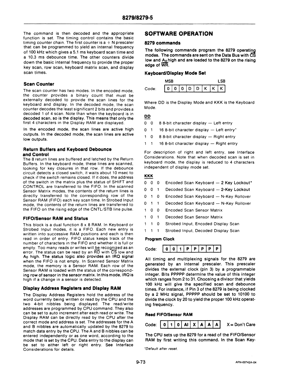
Keyboard/Display Mode Set
MSB
LSB
Code:
lolololDIDIKIKIKI
Where DO is the Display Mode and KKK is the Keyboard
Mode.
DO
o 0 8 8-bit character display - Left
entry
o 16 8-bit
character
display - Left
entry'
o 8
8-bit
character
display - Right
entry
16
8-bit character display - Right
entry
For
description
of
right
and left entry, see Interface
Considerations. Note that when
decoded
scan is set in
keyboard mode, the display
is
reduced to 4 characters
independent
of
display mode set.
KKK
o 0 0 Encoded Scan Keyboard - 2 Key
Lockout·
o 0 Decoded Scan Keyboard - 2-Key
Lockout
o 0 Encoded Scan Keyboard - N-Key Rollover
o Decoded Scan Keyboard - N-Key Rollover
o 0 Encoded Scan Sensor Matrix
o Decoded Scan Sensor Matrix
o Strobed Input, Encoded Display Scan
Strobed Input,
Decoded Display Scan
Program
Clock
All
timing
and
multiplexing
signals
for
the
8279 are
generated
by
an internal prescaler.
This
prescaler
divides
the
external
clock
(pin
3)
by
a
programmable
integer.
Bits
PPPPP
determine
the
value
of
this
integer
which
ranges
from
2
to
31.
Choosing
a
divisor
that
yields
100 kHz
will
give
the
specified
scan and
debounce
times.
For
instance,
if
Pin 3
of
the
8279 is
being
clocked
by
a 2
MHz
signal, PPPPP
should
be set
to
10100
to
divide
the
clock
by
20
to
yield
the
proper
100
kHz
operat-
ing frequency.
Read
FIFO/Sensor RAM
Code: 1 0
11
1 0 1 AI I X I A I A
fA]
X =
Don't
Care
The CPU
sets
up
the
8279
for
a read
of
the
FIFO/Sensor
RAM
by
first
writing
this
command.
In
the
Scan
Key-
'Default
after
reset.
9-73
AFN-00742A-04


