


SINGLE COMPONENT SYSTEM
8021
Functional.
Specifications
The following
is
a functional description
of
the major elements
of
the 8021.
2.5
Program
Memory
The
8021
contains 1 K x 8
of
mask
programmable
ROM. No external
ROM
expansion capability is provided.
2.6
Data
Memory
A 64 x 8 dynamic RAM
is
located on chip for
data storage.
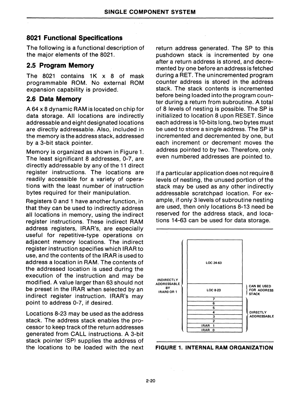
All locations are indirectly
addressable and eight designated locations
are directly addressable. Also, included in
the memory is the address stack, addressed
by a 3-bit stack pointer.
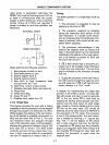
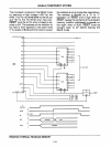
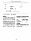
Memory is organized
as
shown in Figure
1.
The least significant 8 addresses, 0-7, are
directly addressable by any
of
the
11
direct
register instructions. The locations are
readily accessible for a variety
of
opera-
tions with the least number
of
instruction
bytes required for their manipulation.
Registers
0 and 1 have another function, in
that they can
be
used
to
indirectly address
all locations in memory, using the indirect
register instructions. These indirect RAM
address registers,
IRAR's, are especially
useful for repetitive-type operations on
adjacent memory locations. The indirect
register instruction specifies which
IRAR to
use, and the contents
of
the I
RAR
is
used to
address a location in RAM. The contents
of
the addressed location is used during the
execution
of
the instruction and may
be
modified. A value larger than 63should not
be preset in the
IRAR when selected by
an
indirect register instruction. IRAR's may
point
to
address 0-7,
if
desired.
Locations 8-23 may be used
as
the address
stack. The address stack enables the pro-
cessor to keep track
ofthe
return addresses
generated from CALL instructions. A 3-bit
stack pointer
(SP)
supplies the address
of
the locations to
be
loaded with the next
2-20
return address generated. The
SP
to
this
pushdown stack is incremented by one
after a return address
is
stored, and decre-
mented by one before
an
address is fetched
during a RET. The unincremented program
counter address is stored in the address
stack. The stack contents
is
incremented
before being loaded into the program coun-
ter during a return from subroutine. A total
of
8 levels
of
nesting
is
possible. The
SP
is
initialized
to
location 8 upon RESET. Since
each address is 10-bits long, two bytes must
be
used to store a single address. The
SP
is
incremented and decremented by one, but
each increment
or
decrement moves the
address pointed to by two. Therefore, only
even numbered addresses are pointed to.
If a particular application does not require 8
levels
of
nesting, the unused portion
of
the
stack may
be
used
as
any other indirectly
addressable scratch pad location. For ex-
ample,
if
only
3 levels
of
subroutine nesting
are used, then only locations 8-13 need
be
reserved
for
the address stack, and loca-
tions 14-63 can
be
used
for
data storage.
INDIRECTLY
ADDRESSABLE
BY
IRARO
OR
1
LOC 24·63
LOC 8-23
7
6
5
4
3
2
IRAR
1
IRAR
0
}
CAN
BE
USED
FOR ADDRESS
STACK
I
DIRECTLY
ADDRESSABLE
FIGURE
1.
INTERNAL
RAM
ORGANIZATION