8259A
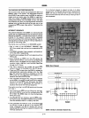
THE CASCADE BUFFER/COMPARATOR
This function block stores and compares the IDs
of
all
8259A's used in the system. The associated three I/O
pins (CASO-2) are outputs when the 8259A is used as a
master and are inputs when the 8259A is used as a
slave. As a master, the 8259A sends the
10
of
the inter-
rupting slave device onto the
CASO-2 lines. The slave
thus selected
will
send Its preprogrammed subroutine
address onto the Data Bus during the next one
or
two
consecutive
INTA pulses.
(See
section "Cascading the
8259A".)
INTERRUPT SEQUENCE
The powerful features
of
the 8259A in a microcomputer
system are
its
programmability and the interrupt routine
addressing
capability. The latter allows direct
or
indirect
jumping
to
the specific interrupt routine requested
without any
polling of the interrupting devices. The nor-
mal sequence of events during
an
interrupt depends on
the type of
CPU
being used.
The events occur as follows in
an
MCS-80/85 system:
1.
One
or
more
of
the INTERRUPT REQUEST lines
(IR7-0) are raised high, setting the corresponding
IRR
bit(s).
2.
The 8259A evaluates these requests, and sends
an
INT
to
the
CPU,
if
appropriate.
3.
The
CPU
acknowledges the INT and responds with
an
INTA pulse.
4.
Upon receiving
an
INTA from the
CPU
group, the
highest priority
ISR
bit
is set, and the corresponding
IRR
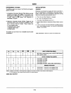
bit is reset. The 8259A will also release a CALL in-
struction code (11001101) onto the 8-bit Data Bus
through
its
07-0
pins.
5.
This CALL instruction will initiate two more INTA
pulses
to
be sent
to
the 8259A from the
CPU
group.
6.
These two INTA pulses allow the 8259A
to
release
its
preprogrammed subroutine address onto the Data
Bus. The lower 8-bit address is released at the first
INTA pulse and and the higher 8-bit address is
re-
leased at the second INTA pulse.
7.
This completes the 3-byte CALL instruction released
by
the 8259A. In the AEOI mode the
ISR
bit is reset at
the end of the third
INTA pulse. Otherwise, the
ISR
bit
remains set
until
an
appropriate
EOI
command is
issued at the end
of
the interrupt sequence.
The events occurring in
an
MCS-86
system are the same
until step
4.
4.
Upon receiving
an
INTA from the
CPU
group, the high-
est priority
ISR
bit is set and the corresponding
IRR
bit is reset. The 8259A does not drive the Data Bus
during
this
cycle.
5.
The MCS-86
CPU
will initiate a second INTA pulse.
During
this
pulse, the 8259A releases
an
8-bit pointer
onto the Data Bus where it is
read
by the
CPU.
6.
This completes the interrupt cycle. In the AEOI mode
the
ISR bit is reset at the end of the second INTA
pulse. Otherwise, the
ISR
bit remains set until
an
appropriate
EOI
command is issued at the end
of
the
interrupt subroutine.
9-41
If no interrupt request is present at step 4
of
either
sequence (i.e., the request was too short in duration) the
8259A
will issue
an
interrupt level
7.
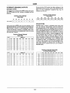
Both the vectoring
bytes and the
CAS lines will look like
an
interrupt level 7
was requested.
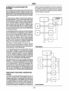
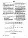
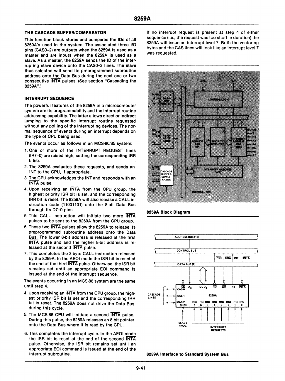
8259A
Block Diagram
CASCADE
{
LINES
,
INTERRUPT
REQuESTS
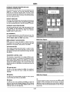
8259A Interface
to
Standard System Bus
I,


