EM1
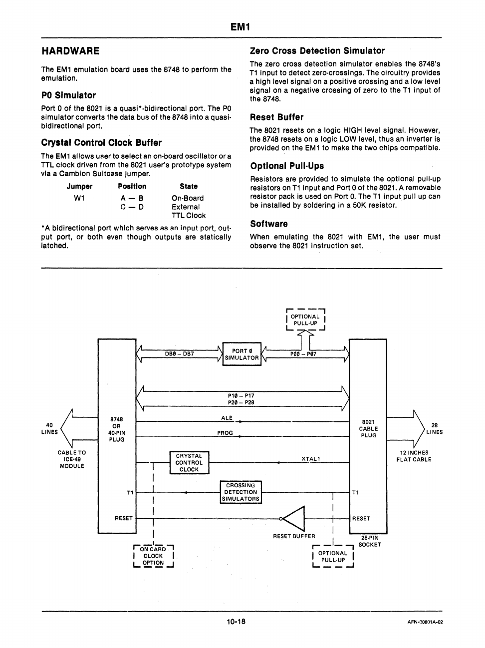
HARDWARE
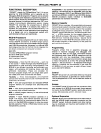
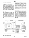
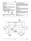
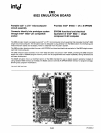
The
EM1
emulation board uses the
8748
to perform the
emulation.
PO
Simulator
Port 0
of
the
8021
Is a quasi"-bldlrectlonal port. The
PO
simulator converts the data bus
of
the
8748
Into a quasi-
bidirectional port.
Crystal Control Clock Buffer
The
EM
1 allows user to select
an
on-board oscillator
or
a
TTL
clock driven from the
8021
user's prototype system
via a
Camblon Suitcase jumper.
Jumper Poaltlon
W1
A-
B
C-D
State
On-Board
External
TIL
Clock
"A
bidirectional port which serves as
an
Input port. out-
put port, or both even though outputs are statically
latched.
DB0-
DB7
Zero Cross Detection Simulator
The zero cross detection simulator enables the 8748's
T1
Input to detect zero-crossings. The circuitry provides
a high
level signal
on
a positive crossing and a low level
signal
on a negative crossing
of
zero to the
T1
Input
of
the 8748.
Reset Buffer
The
8021
resets on a logic HIGH level signal. However,
the 8748 resets on a
logic LOW level, thus an Inverter
Is
provided on the
EM1
to make the two chips compatible.
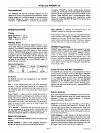
Optional Pull·Ups
Resistors are provided to simulate the optional pull-up
resistors on
T1
input and Port 0
of
the
8021.
A removable
resistor pack is used on Port
O.
The
T1
input
pull
up
can
be
Installed by soldering
In
a 50K resistor.
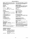
Software
When emulating the
8021
with
EM1,
the user must
observe the
8021
Instruction set.
P10
-
P17
P20-
P28
40
LINES
CABLE TO
ICE-49
MODULE
8748
OR
4()'PIN
PLUG
r-
______________
~A~LE~
__________________
~
PROG
r-1
CRYSTAL
CONTROL
CLOCK
r-
__________
.......
__
-""XTAL 1
Tlr-~-----
.......
----~
r-----------~--~Tl
8021
CABLE
PLUG
RESET t--.-----------------------o<
1------1---1
RESET
'-oiiiCIAFiD
.,
I CLOCK I
L2!!!I~
.J
10-18
. I
RE~ET
BUFFER I 28·PIN
r-
-
-..,
SOCKET
I OPTIONAL I
LP~L~
...J
28
LINES
12 INCHES
FLAT
CABLE
AFN-00801A-02


