MODEL225
FUNCTIONAL DESCRIPTION
Hardware Components
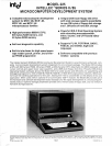
The Intellec Series
11/85
Model
225
is
a highly-
integrated microcomputer development system
consisting of a CRT chassis with a
6-slot cardcage,
power
supply, fans, cables, single floppy disk
drive,
and
two printed circuit cards. A separate,
full
ASCII
keyboard is connected with a cable.
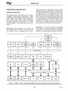
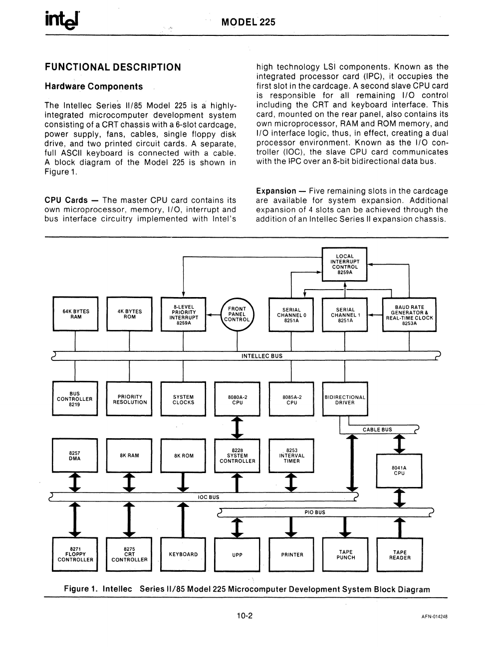
A block diagram of the Model
225
is shown
in
Figure1.
CPU Cards - The master
CPU
card contains its
own microprocessor, memory,
I/O, interrupt and
bus interface circuitry
implemented with Intel's
8·LEVEL
K?
64K BYTES 4K BYTES
PRIORITY
RAM
ROM
PANEL
INTERRUPT
CONTROL
8259A
high technology
LSI
components. Known
as
the
integrated processor card
(IPC), it occupies the
first
slot
in
the cardcage. A second slave
CPU
card
is
responsible for all remaining I/O control
including
the
CRT
and keyboard interface. This
card, mounted
on
the rear panel, also contains its
own microprocessor,
RAM
and
ROM
memory, and
1/0 interface logic, thus,
in
effect, creating a dual
processor envi"ronment. Known
as
the 1/0 con-
troller (IOC), the slave
CPU
card communicates
with the
~PC
over
an
8-bit bidirectional data bus.
Expansion - Five remaining
slots
in
the cardcage
are
available for system expansion. Additional
expansion of 4 slots can be achieved through the
addition of
an
Intellec Series
II
expansion chassis.
LOCAL
INTERRUPT
CONTROL
I t
8259A
•
I
I
SERIAL
SERIAL
BAUD
RATE
CHANNELO
CHANNEL1
~
GENERATOR &
REAL·TIME
CLOCK
8251A
8251A
8253A
I I
?
INTELLEC
BUS
;J
I I
BUS
PRIORITY
SYSTEM
CONTROLLER
8080A·2 8085A·2
BIDIRECTIONAL
8219
RESOLUTION
CLOCKS
CPU CPU
DRIVER
1
I I
CABLE
BUS
?
-.:.II
~
Y
cp
9
8228 8253
DMA
8K RAM
SYSTEM
INTERVAL
CONTROLLER TIMER
8041A
t
f
t
CPU
....
,..
t
~
IOC BUS
,J
...
,..
...
...
,..
?
PIO BUS
?
....
"..
....
"..
8
!
!
f
8271
8275
TAPE
FLOPPY CRT KEYBOARD
PRINTER
TAPE
CONTROLLER CONTROLLER
PUNCH
READER
Figure
1.
Intellec
Series 11/85 Model 225 Microcomputer Development System Block Diagram
10-2
AFN-014248


