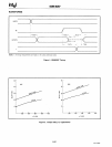
8251A/S2657
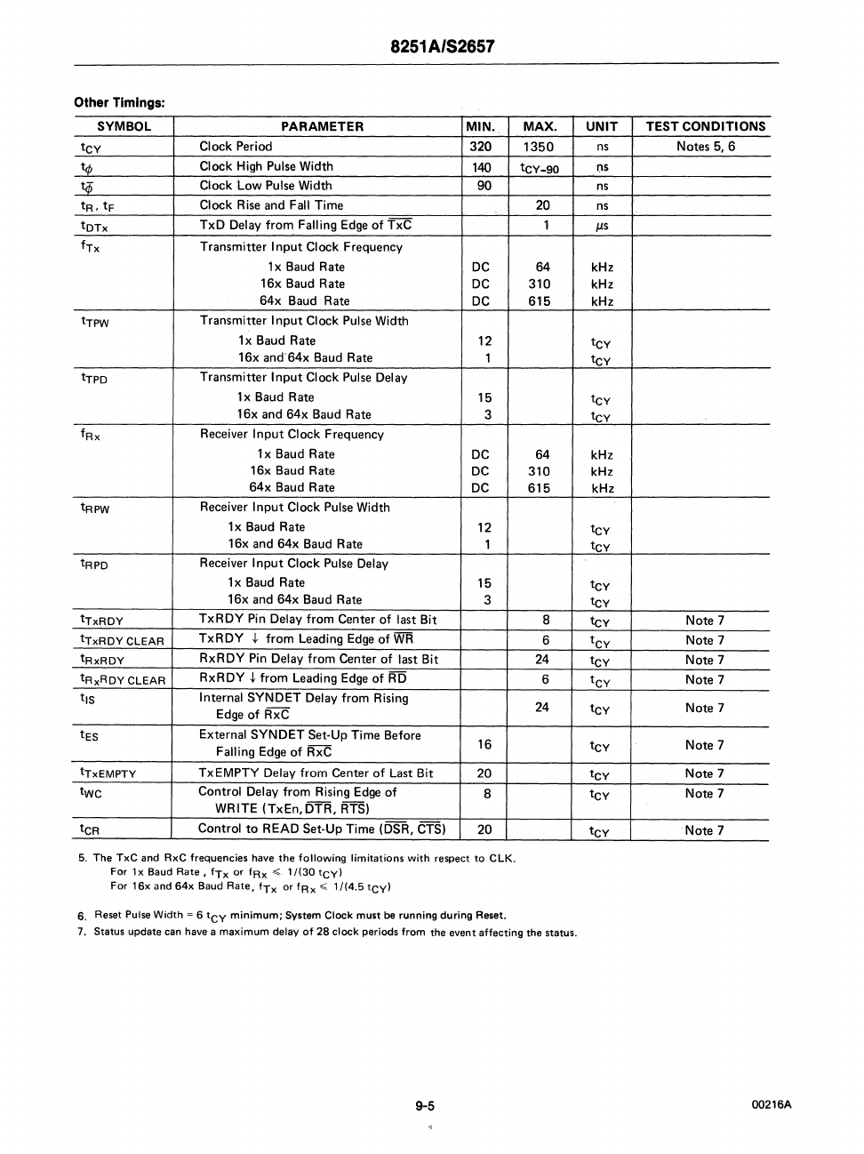
Other
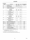
Timings:
SYMBOL
PARAMETER
MIN. MAX.
UNIT
TEST
CONDITIONS
tCY
Clock
Period
320
1350
ns
Notes
5, 6
tq,
Clock
High Pulse Width
140
tCY-90
(IS
1:$
Clock
Low
Pulse Width
90
ns
tR,
tF
Clock
Rise
and
Fall
Time
20
ns
tDTx
TxD
Delay
from
Falling Edge
of
TxC
1
J.Ls
fTx
Transmitter
I
nput
Clock
Frequency
lx
Baud
Rate
DC
64
kHz
16x
Baud
Rate
DC
310
kHz
64x
Baud
Rate
DC
615
kHz
tTPW
Transmitter
I
nput
Clock
Pulse Width
1 x Baud
Rate
12
tCY
16x
and64x
Baud
Rate
1
tCY
tTPD
Transmitter
Input
Clock
Pulse Delay
1 x Baud
Rate
15
tCY
16x
and
64x
Baud
Rate
3
tCY
fRx
Receiver
Input
Clock
Frequency
lx
Baud
Rate
DC
64
kHz
16x
Baud
Rate
DC
310
kHz
64x
Baud
Rate
DC
615
kHz
tRPW
Receiver
Input
Clock
Pulse Width
lx
Baud
Rate
12
tCY
16x
and
64x
Baud
Rate
1
tCY
tRPD
Receiver
Input
Clock
Pulse Delay
lx
Baud
Rate
15
tCY
l6x
and
64x
Baud
Rate
3
tCY
tTxRDY
TxRDY
Pin Delay
from
Center
of
last Bit
8
tCY
Note
7
tTxRDY
CLEAR
TxRDY
~
from
Leading Edge
of
WR
6
tCY
Note
7
tRxRDY
RxRDY
Pin Delay
from
Center
of
last Bit
24
tCY
Note
7
tRxRDY
CLEAR
RxRDY
~
from
Leading Edge
of
RD
6
tCY
Note
7
tiS
Internal
SYNDET
Delay
from
Rising
24
tCY
Note
7
Edge
of
RxC
tES
External
SYNDET
Set·
Up
Time
Before
16
tCY
Note
7
Falling Edge
of
RxC
tTxEMPTY
TxEMPTY
Delay
from
Center
of
Last Bit
20
tCY
Note
7
twc
Control
Delay
from
Rising Edge
of
8
tCY
Note
7
WRITE
(TxEn,DTR,
RTS)
tCR
Control
to
READ
Set-Up
Time
(DSR, CTS)
20
tCY
Note
7
5.
The
TxC
and
RxC
frequencies
have
the
following
limitations
with
respect
to
elK.
For
1 x
Baud
Rate,
fTx
or
fRx
< 11(30
tCY)
For
16x and 64x
Baud
Rate.
fTx
or
fRx < 1/(4.5 tCyl
6.
Reset
Pulse
Width
~
6
tCY
minimum; System Clock must
be
running during Reset.
7.
Status update can have a maximum delay
of
28
clock periods from the event affecting the status.
9-5
00216A


