


inter
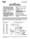
8272
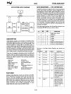
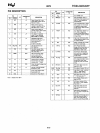
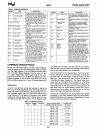
TABLE
2.
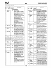
COMMAND MNEMONICS
SYMBOL
NAME
DESCRIPTION
Ao
Address Line 0
AO
controls selection
of
Main Status
Register
(AO=
0)
or
Data
Register
(AO
=
1).
C
Cylinder Number C stands for the current selected Cylinder
track number 0 through
76
of
the medium.
0 Data o stands for the data pattern which
Is
going
to
be
written Into a Sector.
orOo
Data Bus
B-blt Data Bus where
07
is the most
significant bit, and 00 Is the least signlfl'
cant bit.
OSO,OS1
Drive Select
OS
stands
tor
a selected drive number 0
or
1.
oTl
Data length
When N is defined as
OQ,
DTl
stands for
the data
length
which
users are
going
to
read
out
or
write
into
the
Sector.
EOT End
of
Track
EOT
stands for the final Sector number of
a Cylinder.
GPl
Gap Length GPL
stands
for
the
length
of
Gap 3
(spacing between Sectors excluding
VCO
Sync Field).
H Head Address H stands for head number 0
or
1,
as
specified in
10
field.
HOS
Head Select
HOS
stands for a selected
Mad
number 0
or
1
(H
=
HOS
in all command words).
HLT
Head Load Time HLT stands for the head load time in the
FOO
(2
to
254
ms in 2
ms
increments).
HUT Head Unload Time
HUT
stands for the head unload time after
a read
or
write operation has occurred
(16
to
240ms in
16ms
Increments).
MFM
FM
or
MFM Mode If MF is low, FM mode is selected and If
It Is
high, MFM mode Is selected,
MT
Multi·Track If MT
is
high, a multi·track operation is
to
be
performed
(a
cylinder under both
HDO
and
HD1
will be read
or
written).
N Number N stands for the number
of
data bytes
written in a
Sector.
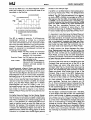
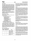
COMMAND DESCRIPTIONS
During the Command
Phase,
the Main Status Register
must
be
polled by the
CPU
before each byte is written
into
the Data Register.
The
010
(OB6)
and
ROM
(OB7)
bits in the Main Status Register must
be
in the
"0"
and
"1"
states respectively, before each byte
of
the com-
mand may
be
written into.the
8272.
The beginning
of
the
execution phase for any
of
these commands will cause
010
and
ROM
to switch
to
"1"
and
"0"
states respective-
ly.
READ DATA
A set of nine
(9)
byte words are required to place the
FOC
into the
Read
Data Mode. After the
Read
Data com·
mand has been issued the
FOC
loads the head (if
it
is in
the unloaded state), waits the specified head settling
time (defined in the Specify Command), and begins
reading
10
Address Marks
and
10
fields. When the cur·
rent sector number ("R") stored in the
10
Register
(lOR)
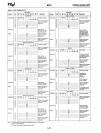
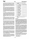
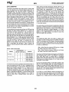
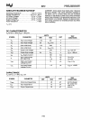
TABLE
3.
TRANSFER CAPACITY
Multl·Track
MFM/FM
Bytes/Sector
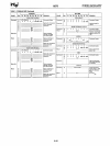
SYMBOL
NAME
DESCRIPTION
NCN
New Cylinder Number NCN stands for a new Cylinder number,
which
Is going
to
be
reached as a result
of
the Seek operation, Desired
position
of
Head.
NO
Non·DMA Mode
NO
stands
for
operation
In
the Non·DMA
Mode,
PCN
Present Cylinder
PCN
stands for the Cylinder number at
Number the completion
of
SENSE INTERRUPT
STATUS
Command. Position of Head at
present time.
R
Record
R stands for the
Sector number, which
will
be read
or
written.
R/W
Read/Write R/W stands for either Read
(R)
or
Write
(IN) aignal.
SC
Sector
SC
Indicates the number
of
Sectors per
Cylinder.
SK
Skip
SK stands for Skip Deleted Data Address
Mark.
SRT Step Rate Time
SRT
stands for the Stepping Rate for the
FDD
(1
to
16ms
In
1 ms Increments).
Stepping Rate applies
to
a1\
drives
(F
= 1 ms, E = 2 ms, etc.).
STO
Status 0
ST
0-3
stand for one
of
four registers
ST
1 Status 1
which store the status information after
ST 2 Status 2
a command has been executed. This
ST 3
Status 3
information
15
available during the result
phase after command execution. These
registers should
not
be confused with the
main status register (selected by
AO
=
0).
ST
0-3
may be read only after a command
has been executed and contain information
relevant
to
that
particular command.
STP
During a Scan operation, If
STP=
1,
the
data in contiguous sectors
Is compared
byte
by
byte with data sent from the
processor (or DMA), and
if
STP=
2,
then
alternate sectors are read and compared.
compares with the sector number
read
off
the diskette,
then the
FOC
outputs data (from the data field) byte-bY-
byte to the main system via the data bus.
After completion of the
read
operation from the current
sector, the Sector Number is incremented by one, and
the data from the next sector
is
read
and
output on the
data bus. This continuous
read
function is called a
"Multi·Sector
Read
Operation." The
Read
Data Com-
mand may
be
terminated by the receipt of a Terminal
Count signal. Upon receipt
of
this signal, the
FOC
stops
outputting data to the processor, but will continue to
read
data from the current sector, check
CRC
(Cyclic
Redundancy Count) bytes,
and
then at the end
of
the
sector terminate the
Read
Data Command.
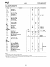
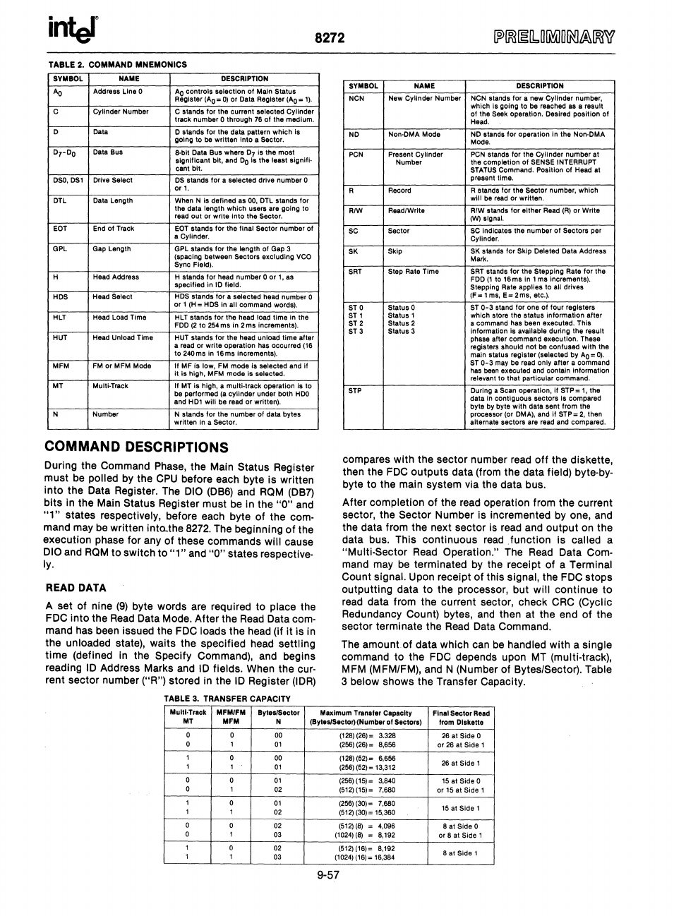
The amount
of
data which
can
be
handled with a Single
command to the
FOC
depends upon
MT
(multi·track),
MFM (MFM/FM), and N (Number of Bytes/Sector). Table
3 below shows the Transfer Capacity.
Maximum Transfer Capacity
Final Sector Read
MT
MFM
N (BytesJSector)(Number
of
Sectors)
from Diskette
0
0 00
(128)
(26)
= 3.328
26
at Side 0
0 1
01
(256)(26) = 8,656
or
26
at Side 1
1
0 00
(128)
(52)= 6,656
26
at Side 1
1
1
01
(256)
(52) = 13,312
0
0
01
(256)(15)= 3,840
15
at Side 0
0
1
02 (512)(15)= 7,680
or
15
at Side 1
1
0
01
(256)
(30)= 7,680
15
at Side 1
1 1
02
(512)
(30)= 15,360
0
0
02
(512)
(8)
= 4.096
8
at
Side 0
0 1
03
(1024)
(8)
= 8,192
or
8 at Side 1
1
0
02 (512)(16)= 8,192
8 at Side 1
1
1
03
(1024)(16)=
16,384
9-57