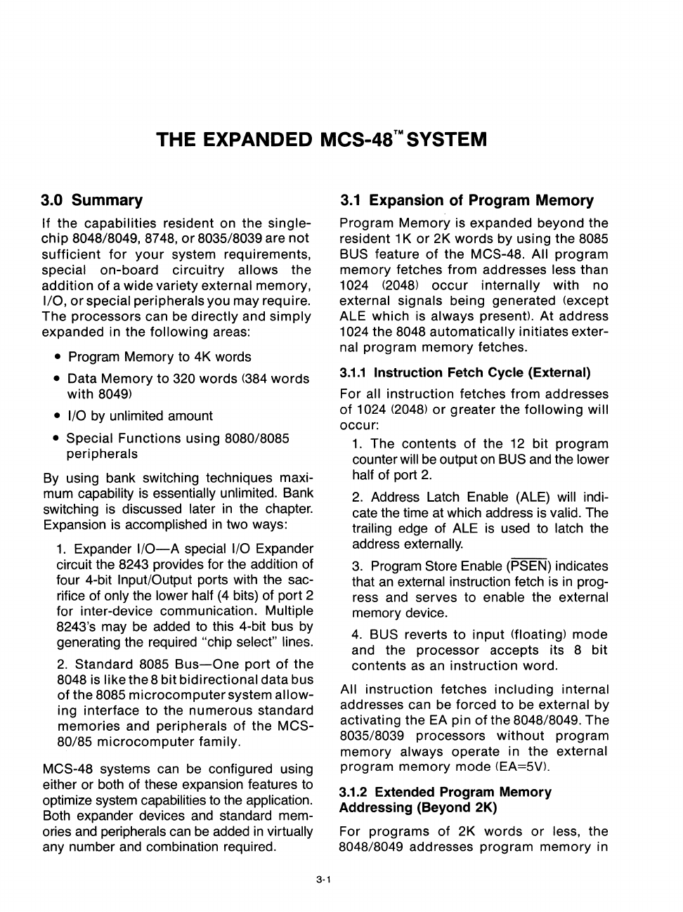
THE
EXPANDED MCS-4S™SYSTEM
3.0 Summary
If the capabilities resident on the single-
chip
8048/8049,8748,
or
8035/8039 are
not
sufficient
for
your
system requirements,
special on-board circuitry allows the
addition
of
a wide variety external memory,
I/O,
or
special peripherals you may require.
The processors can be directly and simply
expanded in the following areas:
• Program Memory to 4K words
• Data Memory to 320 words
(384
words
with
8049)
• I/O
by unlimited amount
• Special Functions using 8080/8085
peripherals
By using bank switching techniques maxi-
mum capability is
essentially unlimited. Bank
switching is discussed later
in
the chapter.
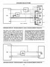
Expansion is accomplished
in
two ways:
1.
Expander
I/O-A
special I/O Expander
circuit the 8243 provides for the addition of
four 4-bit Input/Output ports with the sac-
rifice of only the lower half
(4
bits) of port 2
for inter-device communication.
Multiple
8243's may be added to this 4-bit bus by
generating the required "chip select" lines.
2.
Standard 8085
Bus-One
port
of
the
8048 is like the 8 bit bidirectional data bus
of
the 8085 microcomputer system allow-
ing interface to the numerous standard
memories and
peripherals
of
the MCS-
80/85
microcomputer family.
MCS-48 systems can
be
configured using
either or both of these expansion features to
optimize system capabilities to the application.
Both expander devices
and
standard mem-
ories
and
peripherals
can
be added
in
virtually
any number
and
combination required.
3·1
3.1
Expansion
of
Program Memory
Program Memory is expanded beyond the
resident 1 K
or
2K words by using the 8085
BUS
feature
of
the MCS-48. All program
memory fetches from addresses less than
1024
(2048)
occur
internally with no
external signals being generated (except
ALE which is
always present).
At
address
1024 the 8048 automatically initiates exter-
nal program memory fetches.
3.1.1
Instruction Fetch Cycle (External)
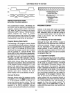
For all instruction fetches from addresses
of
1024
(2048)
or
greater the following will
occur:
1.
The contents of the
12
bit program
counter
will
be
output
on
BUS and the lower
half of port
2.
2.
Address Latch Enable (ALE) will indi-
cate the time at which address is
valid. The
trailing edge of ALE
is
used to latch the
address externally.
3.
Program Store Enable (PSEN) indicates
that
an
external instruction fetch is
in
prog-
ress and serves to
enable the external
memory device.
4.
BUS reverts
to
input (floating) mode
and the processor accepts its 8 bit
contents
as
an
instruction word.
All instruction fetches including internal
addresses can be forced to be external by
activating the
EA
pin
of
the 8048/8049. The
8035/8039 processors
without
program
memory always operate in the external
program memory mode (EA=5Vl.
3.1.2 Extended Program Memory
Addressing (Beyond 2K)
For programs of 2K words
or
less, the
8048/8049 addresses program memory in


