8291
Appendix A
MODIFIED STATE DIAGRAMS
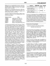
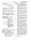
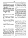
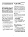
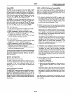
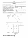
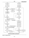
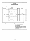
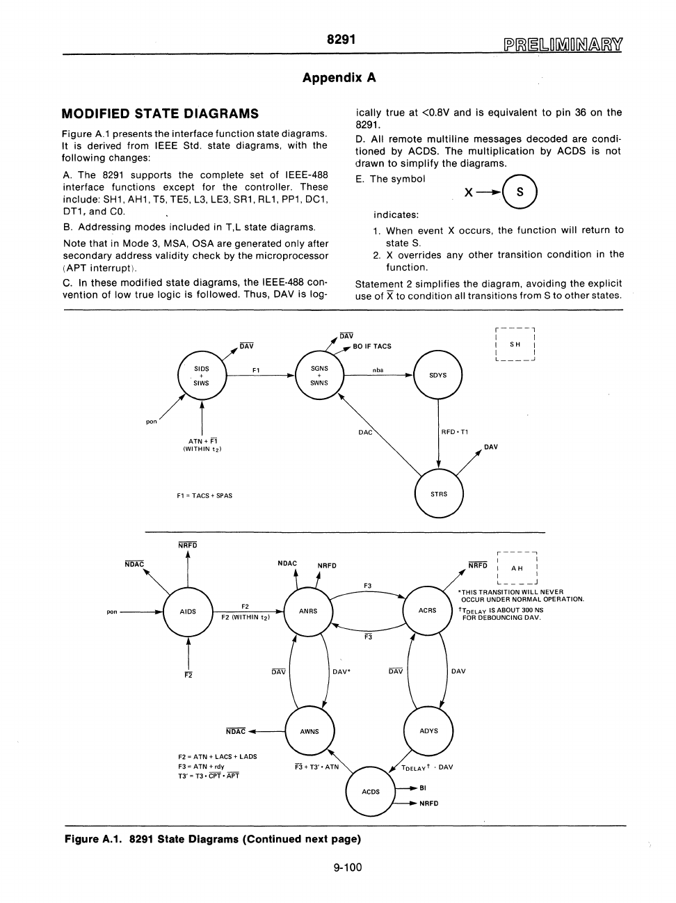
Figure
A.1
presents the interface
function
state diagrams.
It is derived from IEEE Std. state diagrams, with the
following
changes:
A.
The
8291
supports the complete set of IEEE-488
interface functions except for the controller. These
include: SH1, AH1, T5, TE5, L3, LE3, SR1,
RL
1,
PP1,
OC1,
OT1,
and
co.
B.
Addressing modes
included
in T,L state diagrams.
Note
that
in Mode
3,
MSA, OSA are generated only after
secondary address
validity check by the microprocessor
(APT interrupt).
C.
In
these
modified
state
diagrams, the IEEE-488 con·
vention
of
low
true
logic
is
followed.
Thus, OAV is log·
pon
pon----l~
ATN+
i=1
(WITHIN
t2)
F1
'"
TACS + SPAS
F3~ATN+rdy
T3'
'"
T3 •
CPT·
APT
F3
+
T3'·
ATN
ically
true
at <O.8V and
is
equivalent
to
pin
36 on
the
8291.
O.
All remote
multiline
messages
decoded
are
condi·
tioned
by ACOS. The
multiplication
by ACOS
is
not
drawn
to
simplify
the
diagrams.
E.
The
symbol
x--8
indicates:
1.
When event X occurs, the
function
will return
to
state
S.
2.
X overrides any
other
transition
condition
in the
function.
Statement 2
simplifies the diagram, avoiding the
explicit
use of X to
condition
all transitions
from
S
to
other
states.
.
DAV
BI
NRFD
r----l
I I
I SH I
I I
L
____
..J
DAV
r------,
I I
I
AH
I
I I
L
___
_ J
*THIS
TRANSITION WILL NEVER
OCCUR UNDER NORMAL OPERATION.
tTOELAY IS ABOUT 300 NS
FOR
DEBOUNCING
DAV.
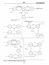
Figure A.1.
8291
State Diagrams (Continued next page)
9-100


