


8272
The "multi·track" function
(MT)
allows the
FDC
to
read
data from both sides
of
the diskette. For a particular
cylinder, data will
be
transferred starting
at
Sector
0,
Side 0
and
completing at Sector
L,
Side 1 (Sector L = last
sector
on
the side). Note, this function pertains to only
one cylinder (the same track)
on
each side
of
the
diskette.
When N
= 0, then DTL de.fines the data length which the
FDC
must treat
as
a sector. If
DTL
is smaller than the ac·
tual
data length in a Sector, the data beyond
DTL
in the
Sector, is not sent to the Data Bus.
The
FDC
reads (inter·
nally)
the complete Sector performing the
CRC
check,
and depending upon the manner
of
command termina·
tion,
may
perform a Multi,·Sector
Read
Operation. When
N is
non·zero, then
DTL
has no meaning and should
be
set to
OFFH.
At the completion
of
the
Read
Data Command, the head
is not
unloaded until after Head Unload Time Interval
(specified in the Specify Command) has elapsed. If the
processor
Issues another command before the head
unloads then the head settling time may
be
saved
be·
tween subsequent reads. This time out is particularly
valuable
when a diskette is copied from one drive to
another.
If
the
FOC
detects the Index Hole twice without finding
the right sector, (indicated in
"R"), then the
FDC
sets
the
NO
(No
Data) flag in Status Register 1 to a 1 (high),
and terminates the
Read
Data Command. (Status
Register 0 also has bits 7 and 6 set to 0 and 1 respective·
Iy.)
After reading the
10
and Data Fields in each sector, the
FDC checks the
CRC
bytes. If a read error is detected
(incorrect
CRC
in
ID
field), the
FDC
sets the
DE
(Data
Er-
ror) flag in Status Register 1 to a 1 (high),
and
if
a
CRC
er-
ror occurs in the Data Field the
FOG
also sets the
DO
(Data Error in Data Field) flag in Status Register 2 to a 1
(high),
and
terminates the
Read
Data Command. (Status
Register 0 also has bits 7
and
6 set to 0
and
1 respec-
tively.)
If
the
FOC
reads a Deleted Data Address Mark
off
the
diskette, and the
SK bit (bit 05 in the first Command
Word) is not set
(SK =
0),
then the
FDC
sets the
CM
(Con-
trol
Mark) flag in Status Register 2 to a 1 (high), and ter-
minates the
Read
Data Command, after reading all the
data in the
Sector. If SK =
1,
the
FDC
skips the sector
with the
Deleted Data Address Mark and reads the next
sector.
During disk data transfers between the
FDC
and the
processor, via the data bus, the FDC must
be
serviced
by the processor every
27
fls
in the
FM
Mode, and every
13
fls in the MFM Mode, or the FDC sets the
OR
(Over
Run)
flag in Status Register 1 to a 1 (high), and ter-
minates the
Read
Data Command.
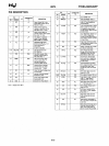
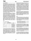
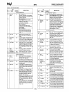
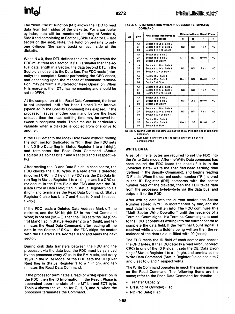
If
the processor terminates a
read
(or write) operation in
the
FDC,
then the
10
Information in the Result Phase is
dependent upon the state
of
the MT bit and
,EOT
byte.
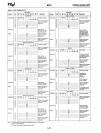
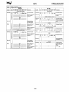
Table 4 shows the values for
C,
H,
R,
and
N,
when the
processor terminates the Command.
TABLE
4.
10
INFORMATION WHEN PROCESSOR TERMINATES
COMMAND'
Final
Sector
Transferred
to
10
Intormatlon
at
Relult
Ph.l.
MT
EOT
Proce.sor C H R N
lA Sector 1
to
25 at Side 0
OF
Sector
1
to
14
at
Side 0
NC
NC
R+1
NC
08 Sector 1
to
7 at Side 0
lA
Sector 26 at Side 0
OF
Sector 15 at Side 0
C+l
NC
R=Ol
NC
08
Sector 8 at Side 0
0
lA
Sector 1
to
25
at Side 1
OF
Sector 1
to
14
at Side 1
NC
NC
R+l
NC
08
Sector 1
to
7 at Side 1
lA
Sector
26
at Side 1
OF
Sector
15
at Side 1
C+l
NC
R=Ol
NC
08
Sector 8 at Side 1
lA
Sector 1
to
25
at Side 0
OF
Sector 1
to
14
at Side 0
NC NC
R+l
NC
08
Sector 1
to
7
at
Side 0
lA
Sector 26 at Side 0
OF
Sector
15
at Side 0
NC
LSB
R=Ol
NC
08
Sector 8 at Side 0
1
lA
Sector 1
to
25 at Side 1
OF
Sector
1
to
14
at
Side 1
NC NC
R+l
NC
08
Sector 1
to
7 at Side 1
lA
Sector 26 at Side 1
OF
Sector 15 at Side 1
C+l
LSB
R=Ol
NC
08
Sector 8
at
Side 1
Notes;
1.
NC
(No Change): The same value as the one
at
the beginning
of
command
execution.
2.
LSB (Least Significant Bit): The least
significant
bit
of
H
Is
complemented.
WRITE
DATA
A set
of
nine
(9)
bytes are required
to
set the
FOG
into
the Write Data mode. After the Write Data command has
been issued the
FDC
loads the head (if
it
is in the
unloaded state), waits the specified head settling time
(defined in the
Specify Command), and begins reading
10
Fields. When the current sector number
(UR"),
stored
in the
10
Register
(lOR)
compares with the sector
number read
off
the diskette, then the
FDC
takes data
from the processor byte-by-byte via the data bus, and
outputs
it
to the
FDD.
After writing data into the current sector, the Sector
Number stored in
"R"
is incremented by one, and the
next data
field is written into. The FDC continues this
"Multi-Sector Write Operation" until the issuance of a
Terminal Count signal. If a Terminal Count signal is sent
to the FDC
it continues writing into the current sector to
complete the data field. If the Terminal Count
signal
is
received
while a data field is being written then the
re-
mainder
of
the data field is filled with
00
(zeros).
The
FDC
reads the
10
field
of
each sector and checks
the
CRC
bytes. If the FDC detects a read error (incorrect
CRC)
in one
of
the
10
Fields,
it
sets the
DE
(Data Error)
flag
of
Status Register 1 to a 1 (high), and terminates the
Write Data Command.
(Status Register 0 also has bits 7
and 6 set to
0
and
1 respectively.)
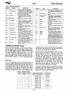
The Write Command operates in much the same manner
as the
Read
Command. The following items are the
same; refer to the
Read
Data Command for details:
•
Transfer Capacity
•
EN
(End
of Cylinder) Flag
•
NO
(No Data) Flag
9-58