


inter
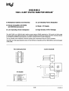
8031/8051/8751
The
8051
provides a non-paged Program Memory
address space to accommodate
relocatable code.
Conditional branches are performed relative to the
Program Counter. The register-indirect jump permits
branching relative to a 16-bit base register with
an
offset provided by
an
8-bit index register. Sixteen-bit
jumps and
calls permit branching to any location
in
the contiguous 64K Program Memory address
space.
The
8051
has five methods
for
addressing source
operands: Register, Direct, Register-Indirect,
Im-
mediate and Base-Register- plus Index-Register-
Indirect Addressing. The first three methods can be
used
for
addressing destination operands. Most
instructions have a "destination, source" field that
specifies the data type, addressing methods and
operands
involved.
For
operations
other
than
moves, the destination operand is also a source
operand.
Registers in the four 8-Register Banks can
be
accessed through Register, Direct, or Register-
Indirect Addressing; the 128 bytes
of
Internal Data
RAM through Direct or Register-Indirect Addressing;
and the Special Function Registers through Direct
Addressing. External Data Memory is accessed
through
Register-Indirect Addressing. Look-Up-
Tables
resident
in
Program Memory can be accessed
through Base-Register- plus Index-Register- Indirect
Addressing.
The
8051
is
classified
as
an
8-bit machine since the
internal ROM, RAM, Special Function Registers,
Arithmetic/Logic Unit and external data bus
are
each
8-bits wide. The
8051
performs operations on bit,
nibble, byte and double-byte data types.
The
8051
has extensive facilities
for
byte transfer,
logic, and integer arithmetic operations. It excels at
bit
handling since data transfer,
logic
and
condi-
tional branch operations can be performed directly
on Boolean variables.
The
8051's
instruction set
is
an
enhancement
of
the instruction set familiar to MCS-48 users. It
is
enhanced to allow expansion of on-Chip CPU
peripherals and to optimize byte efficiency and
execution speed. Op codes were reassigned to add
new high-power operations and to permit new
addressing modes which make the old operations
more orthogonal. Efficient use
of
program memory
results from
an
instruction set consisting
of
49
single-byte,
45
tWO-byte
and
17
three-byte instruc-
tions. When using a
12
MHz oscillator,
64
instructions
execute in
1/.1s
and
45
instructions execute in
'2/.Js.
The remainin,g instructions (multiply and divide)
require only
4/.1s.
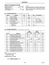
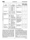
The number of bytes in each instruc-
tion and the number
of
oscillator periods required
for execution are listed in the appended
8051
Instruc-
tion Set Summary.
7-3
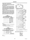
2.2
ON-CHIP
PERIPHERAL
FUNCTIONS
Thus far only the CPU and memory spaces
of
the
8051
have
been described. In addition to the
CPU
and memories,
an
interrupt system, extensive I/O
facilities,
and several peripheral functions are inte-
grated on-Chip to relieve the CPU of repetitious,
complicated or time-critical tasks and to permit
stringent
real-time control of external system inter-
faces. The extensive I/O facilities include the I/O
pins, parallel I/O ports, bidirectional address/data
bus and the serial port for I/O expansion. The
CPU
peripheral functions integrated on-chip are the two
16-bit counters and the
serial port. All
of
these work
together to greatly boost system performance.
2.2.1
Interrupt
System
External events and the real-time-driven on-phip
peripherals require service by the
CPU
asynchronous
to the execution of any
particular section
of
code.
To
tie the asynchronous activities
of
these functions
to normal program execution, a sophisticated mul-
tiple-source,
two-priority~level,
nested interrupt sys-
tem
is
provided. Interrupt response latency ranges
from
3ps to
711S
when using a
12
MHz crystal.
The
8051
acknowledges interrupt requests from
five sources: Two from external sources
via
the
INTO
and
iN'R
pins, one from each of the two internal
counters and one from the serial I/O port. Each
interrupt vectors to a separate
location in Program
Memory for its service program. Each
of
the five
sources can
be
assigned
to
either of two priority
levels and can
be
independently enabled and dis-
abled. Additionally all enabled
sources can
be
globally
disabled
or enabled. Each external interrupt
is
pro-
grammable
as
either level- or transition-activated
and is
active-low to allow the "wire or-ing" of several
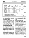
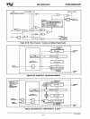
interrupt sources to the input pin. The interrupt
system
is
shown diagrammatically in Figure
2.2
2.2.2 1/0 Facilities
The
8051
has
instructions that treat its
32
I/O lines
as
32
individually addressable bits and
as
four
parallel 8-bit ports addressable
as
Ports
0,1,2
and
3.
Ports
0,
2 and 3 can also assume other functions.
Port 0 provides the
multiplexed low-order address
ahd data bus used for expanding the
8051
with
standard memories and
peripherals. Port 2 provides
the high-order address bus when expanding the
8051
with external Program Memory or more than
256
bytes
of
External Data Memory. The pins of
Port 3 can be configured individually to provide ex-
ternal interrupt request inputs, counter inputs, the
serial port's receiver input and transmitter output,
and to generate the control signals used for reading
and writing External Data Memory. The generation
or use
of
an
alternate function on a Port 3 pin
is
done automatically by the
8051
as
long
as
the pin
AFN-ol482A-03