intel'
8272
SCAN COMMANDS
The SCAN Commands allow data which
is
being read
from the diskette
to
be
compared against data which is
being supplied from the main system (Processor in
NON-DMA mode, and DMA Controller in DMA
mOde).
The FDC compares the data on a byte-by-byte basis, and
looks for a sector
of
data which meets the conditions of
DFDD = Dprocessor, DFDD';; Dprocessor, or
DFDD;;'
Dprocessor·
Ones complement arithmetic is used for comparison
(FF = largest number,
00
= smallest number). After a
whole sector
of
data is compared,
if
the conditions are
not
met, the sector number is incremented
(R
+
STP
-+
R),
and the scan operation is continued. The scan opera·
tion continues until one
of
the following conditions oc·
cur; the conditions for scan are met (equal, low, or high),
the last sector
on
the track is reached
(EOT),
or
the ter-
minal count signal is received.
If
the conditions for scan are met then the FDC sets the
SH
(Scan Hit) flag of Status Register 2
to
a 1 (high), and
terminates the
Scan Command.
If
the conditions for
scan are not met between the starting sector
(as
specified by
R)
and the last sector on the cylinder
(EOT),
then the FDC sets the
SN
(Scan Not Satisfied) flag of
Status Register 2
to
a 1 (high), and terminates the Scan
Command. The receipt of a TERMINAL COUNT signal
from the Processor or DMA Controller during the scan
operation will cause the FDC
to
complete the com·
parison of the particular byte which is in process, and
then
to
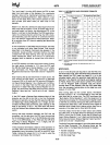
terminate the command. Table 6 shows the
status of bits
SH
and
SN
under various conditions of
SCAN.
TABLE
6.
SCAN STATUS CODES
STATUS REGISTER 2
COMMAND
BIT2=SN
BIT3=SH
COMMENTS
Scan Equal
0 1
OF
DO
=
OProcessor
1
0
OF
DO
=t=
0processor
0 1
DFDD
=
Dprocessor
Scan
low
or
Equal
0
0
DFDD
< Dprocessor
1 0
DFOD
1:
Dprocessor
0
1
DFDD
=
Dprocessor
Scan
Hlghor
Equal
0 0
DFDD
>
Dprocessor
1
0
DFDD
~
Dprocessor
If
the FDC encounters a Deleted Data Address Mark
on
one
of
the sectors (and SK =
0),
then
it
regards the sec·
tor
as the last sector
on
the cylinder, sets
CM
(Control
Mark) flag
of
Status Register 2
to
a 1 (high) and ter·
minates the command. If
SK=
1,
the FDC skips the sec·
tor
with the Deleted Address Mark, and reads the next
sector.
In
the second case
(SK
=
1),
the FDC sets the
CM
(Control Mark) flag of Status Register 2 to a 1 (high) in
order
to
show that a Deleted Sector
had
been en·
countered.
9-60
When either the
STP
(contiguous sectors
STP
=
01,
or
alternate sectors
STP =
02
sectors are
read)
or the
MT
(Multi-Track) are programmed,
it
is necessary
to
remember that the last sector on the track must be read.
For example, if
STP
=
02,
MT
=
0,
the sectors are
numbered sequentially 1 through
26,
and we start the
Scan Command at sector
21;
the following will happen.
Sectors
21,
23,
and
25
will
be
read,
then.the next
sector
(26)
will be skipped and the Index Hole will be en·
countered before the
EOT
value
of
26
can
be
read. This
will result in
an
abnormal termination
of
the command.
If the
EOT
had been set at
25
or the scanning started at
sector
20,
then the Scan Command would
be
completed
in a normal manner.
During the
Scan Command data is supplied by either the
processor or DMA Controller for comparison against the
data read from the diskette.
In order to avoid having the
OR
(Over
Run)
flag set in Status Register
1,
it
is nec-
essary
to
have
the data available in less than
27
JJs
(FM
Mode) or
13
JJS
(MFM Mode). If
an
Overrun occurs the
FDC terminates the command.
SEEK
The read/write head within the FDD is moved from
cylinder
to
cylinder under control
of
the Seek Command.
The FDC compares the
PCN
(Present Cylinder Number)
which is the current head position with the NCN (New
Cylinder Number), and performs the following operation
if
there is a difference:
PCN
< NCN: Direction signal
to
FDD
set
to
a 1 (high),
and
Step Pulses are issued. (Step
In.)
PCN
> NCN: Direction signal to
FDD
set
to
a 0 (low),
and
Step Pulses are issued. (Step Out.)
The rate at which Step Pulses are issued is controlled by
SRT
(Stepping Rate Time) in the SPECIFY Command.
After each
Step Pulse is issued
NCN
is compared
against
PCN,
and when NCN =
PCN,
then the
SE
(Seek
End)
flag is set in Status Register 0 to a 1 (high), and the
command is terminated.
During the Command Phase of the
Seek operation the
FDC
is in the FDC
BUSY
state, but during the Execution
Phase
it
is in the NON
BUSY
state. While the FDC is in
the
NON
BUSY
state, another Seek Command may
be
issued, and in this manner parallel seek operations may
be
done on up
to
4 Drives at once.
If
an
FDD is in a NOT READY state at the beginning
of
the command execution phase or during the seek opera-
tion, then the NR
(NOT
READY)
flag is set in Status
Register 0 to a 1 (high), and the command is terminated.


