8'255A18255A·5
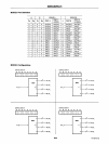
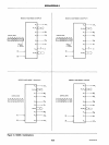
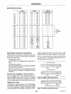
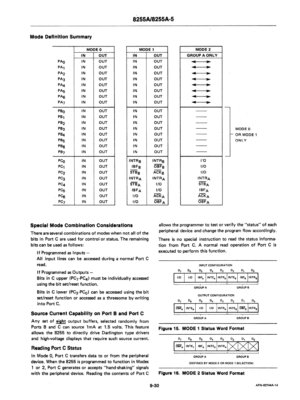
Mode Definition Summary
MODE a
MODE'
MODE 2
IN
OUT
IN
PAo
IN
OUT
IN
PAl
IN OUT IN
PA2
IN OUT IN
PA3
IN
OUT
IN
PA4
IN
OUT
IN
PAS
IN OUT
IN
PAa
IN OUT
IN
PA7
IN OUT IN
PBa
IN
OUT IN
PB,
IN
OUT
IN
PB2
IN OUT
IN
PB3
IN OUT IN
PB4
IN OUT IN
PBS
IN
OUT
IN
PBa
IN OUT
IN
PB7
IN
OUT
IN
PCa
IN OUT
INTRB
PC,
IN OUT
IBFB
PC2
IN OUT
STBB
PC3
IN OUT
INTRA
PC4
IN
OUT
rnA
PCs
IN
OUT
IBFA
pca
IN OUT
I/O
PC7
IN
OUT
I/O
Special Mode Combination Considerations
There are several combinations
of
modes when
not
all
of
the
bits
in
Port C are used for control
or
status. The remaining
bits can be used
as
follows:
If Programmed
as
Inputs -
All
input lines can be accessed during a normal Port C
read.
If Programmed
as
Outputs -
Bits
in
C upper
(PC7-PC41
must be individually accessed
using the bit set/reset function.
Bits
in
Clower
(PC3-PCol can be accessed using the bit
set/reset function or accessed as a threesome by writing
into Port
C.
Source Current Capability on Port B and Port C
Any set of eight output buffers, selected randomly from
Ports
Band
C can source 1mA at 1.5 volts. This feature
allows the
"8255
to
directly drive Darlington type drivers
and high-voltage displays
that
require such source current.
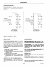
Reading Port C Status
In
Mode 0, Port C transfers data to
or
from the peripheral
device. When the 8255
is
programmed
to
function
in
Modes
1
or
2, Port C generates
or
accepts "hand-shaking" signals
with
the
peripheral device. Reading the contents
of
Port C
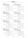
OUT
GROUPAONLV
OUT
..
~
.
OUT
-
OUT
..
~
OUT
---
OUT
-
OUT
---
OUT
---
OUT
---
OUT
OUT
OUT
OUT
OUT
OUT
OUT
OUT
--
--
--
--
--
--
--
--
1
MODE 0
OR
MODE 1
J ONLY
INTRB
I'D
OBFB
I/O
ACKB
I/O
INTRA
INTRA
I/O
STBA
I/O
IBFA
ACKA
ACKA
OBFA
OBFA
allows the programmer
to
test
or
verify the "status" of each
peripheral device and change the program flow accordingly.
There
is
no special instruction
to
read the status informa-
tion from Port
C.
A normal read operation
of
Port C
is
executed
to
perform th
is
fu
nction.
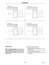
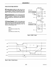
INPUT
CONFIGURATION
OUTPUT
CONFIGURATION
i
GRQUPA
" j ,
GROUPS
Figura
1.5.
MODE 1
Status
Word Format
01
0
6
Os
04 03
D2
0,
Do
I
OBF.
IINTE,
IIBFA
IINTE·IINTR
A
t><IXk><1
,
i"'
GROUP
A
GROUP
8
(DEFINED
BY
MODe
0 OR MODE 1 SELECTION)
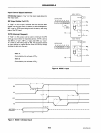
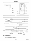
Figura 18.
MODE
2
Statu.
Word Format
9-30
AFN-00744A-14


