


8291
8291
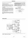
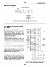
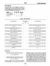
SYSTEM DIAGRAM
r - - -
-,
OREO
I
DMA
I
c(g~il~~~LLE)R
I~
__
D_AC_K_~L""::~~:::':'..J
L
_____
..I
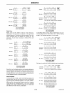
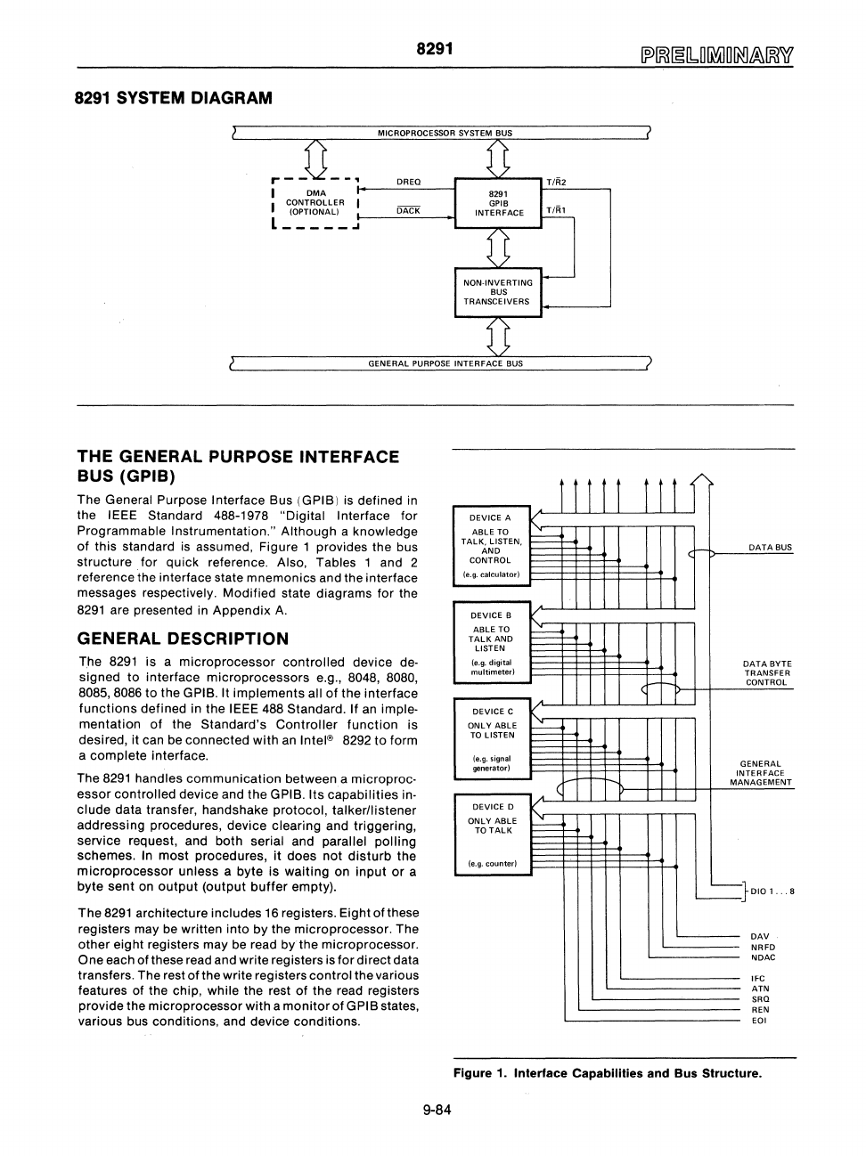
THE GENERAL PURPOSE INTERFACE
BUS (GPIB)
The General Purpose Interface Bus (GPIB)
is
defined in
the
IEEE Standard 488-1978 "Digital Interface
for
Programmable Instrumentation."
Although
a knowledge
of
this standard
is
assumed, Figure 1 provides the bus
structure for quick reference.
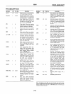
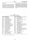
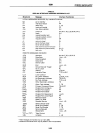
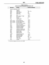
Also, Tables 1 and 2
reference the interface state mnemonics and the interface
messages respectively. Modified state diagrams for the
8291
are presented in Appendix
A.
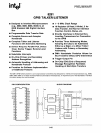
GENERAL DESCRIPTION
The
8291
is
a
microprocessor
controlled
device de-
signed
to
interface
microprocessors
e.g., 8048, 8080,
8085,8086
to
the GPIB. It
implements
all
of
the interface
functions
defined in the IEEE 488 Standard. If an imple-
mentation
of
the Standard's
Controller
function
is
desired, it can be connected
with
an
Intel® 8292
to
form
a
complete
interface.
The
8291
handles
communication
between a microproc-
essor
controlled device and
the
GPIB. Its capabilities in-
clude
data transfer, handshake
protOCOl,
talkerllistener
addressing procedures, device clearing and triggering,
service request, and both
serial and parallel
polling
schemes. In
most
procedures, it does
not
disturb
the
microprocessor
unless a byte is
waiting
on
input
or
a
byte sent
on
output
(output
buffer
empty).
The
8291
architecture includes
16
registers. Eight of these
registers may be written into
by
the microprocessor. The
other
eight registers may be read by the microprocessor.
One each of these read and write registers
is
for
direct data
transfers. The rest
of
the write registers
control
the various
features of the chip,
while the rest
of
the read registers
provide the microprocessor
with
a
monitor
of
GPIB states,
various bus conditions, and device conditions.
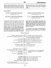
DEVICE
A
ABLE
TO
TALK,
LISTEN,
AND
CONTROL
(e.g.
calculator)
DEVICE B
ABLE TO
TALK
AND
LISTEN
(e.g. digital
multimeterl
DEVICE C
ONLY
ABLE
TO
LISTEN
(e.g.
signal
generator)
DEVICE 0
ONLY
ABLE
TO
TALK
(e.g. counter)
r r r r r
I
t-
I
r--
I
t-
(
I
t-
r r 1 f
DATA
BUS
DATA
BYTE
TRANSFER
(I-t--
CONTROL
GENERAL
INTERFACE
MANAGEMENT
~}DIOl
.
..
8
DAV
NRFD
NDAC
IFC
ATN
SRO
REN
EOI
Figure
1_
Interface Capabilities and
Bus
Structure_
9-84