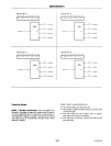
8255A18255A·5
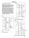
CONTROL
WORD
#12
0,
0
6
05 04
D3
02
0,
DO
I ' I I I
I,
I 0 I 0 I 0 I
A
0
,8
I
PA,·PA
O
B2SSA
1
0
I
"
0 0
c
,
PC,.PC
4
pe
3
,pe
a
8
B
PB,.PB
o
CONTROL
WORD
...
is
0,.
D.
Da D4 D3
02
0,
DO
I I I I I I I 0 I ' I
A
8
PA,·pAo
B25SA
c{
I
' ,
0
0
4
8
B
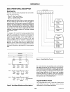
Operating
Modes
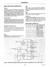
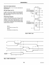
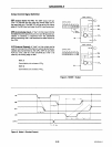
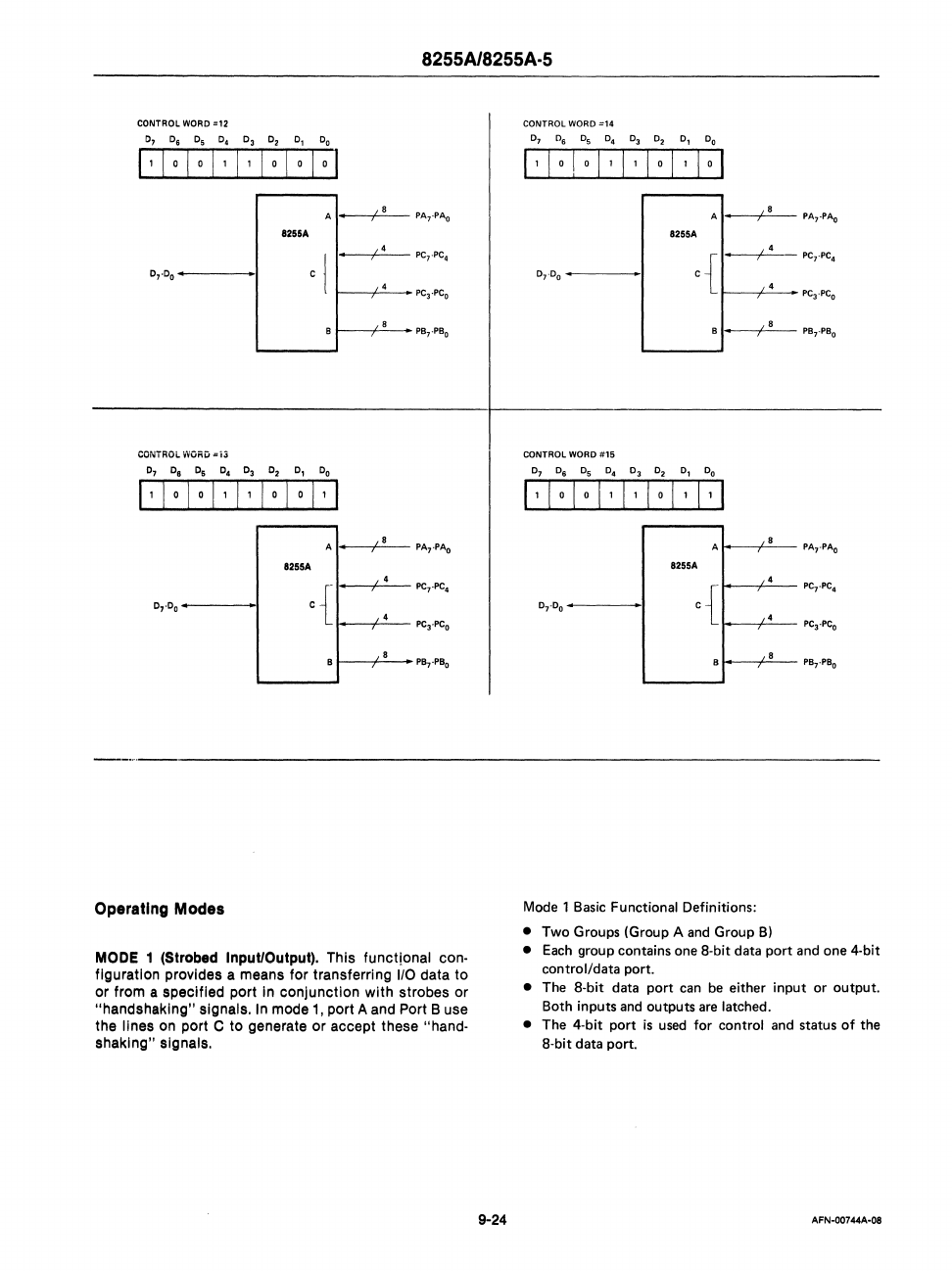
MODE 1 (Strobed Input/Output). This functional con-
figuration provides a means for transferring
1/0
data to
or from s specified port
In
conjunction with strobes or
"handshsklng" signals.
In
mode
1,
port A
and
Port B
use
the lines
on
port C to generate or accept these "hand-
shaking" signals.
9-24
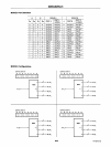
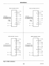
CONTROL WORD
=14
0,
0
6
05 04 03 02
D,
00
I ' I 0 I 0 I ' I ' I 0 I ' I 0 I
A
0
I
,8
PA,·pAo
8211A
c{
0
I
' ,
PC,·PC
4
0,.°
0
Pe
3
,pe
O
B
,8
I
PB,·PB
o
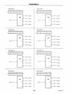
CONTROL WORD
#15
0,
0
6
05
D4
03
02
0,
DO
I ' I 0 I 0 I ' I ' I 0 I ' I I
A
8
8211A
4
0 .
c{
4
Pe,.pc;,
8
8
P..,.P8,
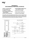
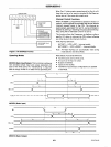
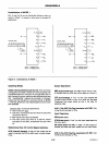
Mode
1
Basic
Functional Definitions:
• Two Groups (Group A and Group
B)
•
Each
group contains one a-bit data port and one 4-bit
control/data port.
• The a-bit data port can
be
either input or output.
Both inputs and outputs are latched.
• The 4-bit port
is
used for control and status of the
a-bit data port.
AFN-00744A-08


