


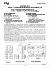


8031/8051/8751
event counter and one 8-bit time-interval counter
(Mode
3).
When
counter 0 is in Mode
3,
counter 1
can
be programmed to any
of
the three aforementioned
modes, although it cannot set an interrupt request
flag
or
generate an interrupt. This mode is useful
because counter 1's overflow can
be
used
to
pulse
the serial port's transmission-rate generator. Along
with their multiple operating modes and 16-bit pre-
cision, the counters can also handle very high input
frequencies. These range from
0.1
MHz to
1.0
MHz
(for
1.2
MHz to
12
MHz crystal) when programmed
for
an
input that is a division by
12
of the oscillator
frequency and from
0 Hz
to
an
upper limit
of
50
KHz
to 0.5 MHz (for 1.2 MHz to
12
MHz crystal) when
programmed
for
external inputs. Both internal and
external inputs can
be
gated to the counter by a
second
external
source
for
directly
measuring
pulse widths.
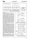
The counters
are
started and stopped under software
contro/.
Each
counter sets its interrupt request flag
when it overflows from all ones to all zeros (or auto-
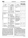
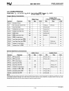
reload value). The operating modes and input sources
are
summarized in Figures 2.4A
and
2.4B.
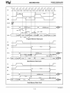
The effects
of the configuration flags and the status flags are
shown in Figures 2.5A and
2.5B.
2.2.4
Serial Communications
The
8051
has
a serial I/O port that is useful for
serially linking peripheral devices
as
well
as
multiple
8051s
through standard asynchronous protocols with
full-duplex operation. The serial port also
has
a
synchronous mode for expansion of
I/O lines using
CMOS
and
TTL shift registers. This hardware serial
communications interface
saves
ROM
code
and
permits a much higher transmission rate than could
be
achieved through software.
In
response to a serial
port interrupt request the
CPU
has
only to read/write
the serial port's buffer to service the serial link.
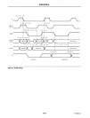
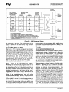
A block diagram of the serial port
is
shown in Figure
2.6.
Methods for linking UART (universal asynchro-
nous receiver/transmitter) devices are shown in
GATE
COUNTER/TiMER
RUN
TO-----+_'
XTAL1
OVERFLOW
(INTERRUPT
'--
______
.J
-
~~~~~ST)
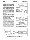
• 8-BIT TIMER/COUNTER WITH PRESCALER
• 16-81T TIMER/COUNTER
•
8-BIT
AUTO·RELOAD
TIMER/COUNTER
PULSE
TO
SERIAL
PORT
Figure
2.4.A
Timer/Event
Counter
Modes
0,
1 and 2
•
8-BIT
TIMER/COUNTER
OVERFLOW
(INTERRUPT
REQUEST)
"-
___
J
_FLAG
1
L-----.OVERFLOW
•
8-BIT
TIMER
(INTERRUPT
REQUEST)
FLAG 0
PULSE
TO
SERIAL
PORT
Figure 2.4.B Timer/Event Counter 0
In
Mode 3
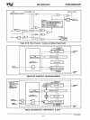
INTERRUPT REQUEST
COUNTER 0
MODE
0:
.·BIT
TIMER WITH 5·BIT PRESCALER/
.·BIT
COUNTER WITH 5·BIT PRESCALER
MODE
1:
16·BIT TIMER/COUNTER
MODE
2:
.·BIT
AUTO·RELOAD TIMER/COUNTER
MODE
3:
.·BIT
TIMER COUNTER
(TLO)
Figure
2.S.A
Timer/Counter
0
Control
and Status Flag
Circuitry
AFN·01462A·06
7-6