


8253/8253-5
8253
READIWRITE
PROCEDURE
Write
Operations
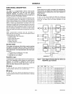
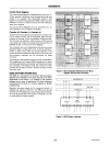
The systems software must program each counter
of
the
8253 with the mode and quantity desired.
The program-
mer must write out to the 8253 a
MODE contrel word and
the programmed number
of
count register bytes
(1
or
2)
prior
to
actually using the selected counter.
The actual order
of
the programming is quite flexible.
Writing out
of
the MODE control word can be in any
sequence
of
counter selection, e.g., counter
#0
does not
have
to
be
first
or
counter
#2
last. Each counter's MODE
control word register has a separate address
so
that its
loading
is
completely sequence independent.
(SCO,
SC1)
The loading
of
the Count Register with the actual count
value, however, must
be
done in exactly the sequence
programmed in the
MODE control word
(RLO,
RL
1).
This
loading
of
the counter's
count
register
is
still sequence
independent
like the MODE control word loading, but
when a selected count register is to
be
loaded it
!!!..!!§!
be
loaded with the number
of
bytes programmed in the
MODE control word
(RLO,
RL
1).
The one
or
two bytes to
be loaded in the
count
register do not have to follow the
associated
MODE control word. They can be programmed
at any time following the
MODE control word loading
as
long
as
the correct number
of
bytes is loaded in order.
All counters are down counters. Thus, the value loaded
into
the count register will actually be decremented.
Loading
all zeroes into a count register will result in the
maximum
count
(2
'6
for
Binary
or
10'for
BCD). In MODE 0
the new count will not restart until the load
has
been
completed.
It will accept one
of
two
bytes depending on
how
the MODE control words
(RLO,
HL
1)
are program-
med. Then proceed with the restart operation.
9-12
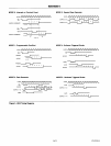
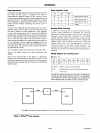
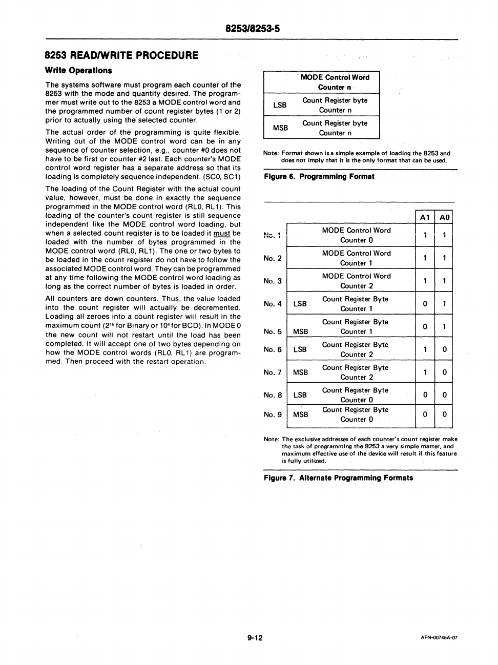
MODE
Control Word
Counter·
n·
LSB
Col,lnt
Register
byte
Counter n
MSB
Cou
nt Register byte
Counter n
Note:
Format
shown is a simple example of loading
the
8253
and
does
not
imply
that
it
is
the
only
format
that
can be used.
Figure
6.
Programming
Format
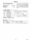
No.1
MODE Control Word
Counter
0
I I
No.2
MODE Control Word
1
1
Counter 1
MODE Control Word
1
1
Counter
2
No.3
LSB
Count
Register
Byte
0
1
Counter 1
No.4
Count
Register
Byte
0
1
MSB
Counter 1
No.5
LSB
Count Register Byte
1
0
Counter 2
No.6
MSB
Count
Register
Byte
1
0
Counter 2
No. 7
LSB
Count
Regist~r
Byte
0 0
Counter 0
No.8
MSB
Count
Register
Byte
0 0
Counter 0
No.9
Note:
The
exclusive addresses
of
each counter's
count
register make
the task
of
programming the
8253
a very simple matter. and
maximum
effective
use
of
the device
will
result if this feature
is
fully utilized.
Figure
7.
Alternate
Programming
Formats
AFN-00745A-G7