


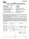
18049/8039
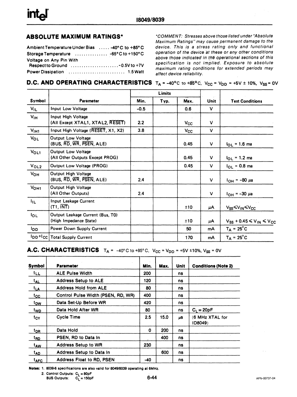
ABSOLUTE MAXIMUM RATINGS·
AmbientTemperatureUnderBias
.....
-40'C
to
+SS'C
Storage Temperature
...............
-6S'C
to
+lS0'C
Voltage on Any Pin With
Respectto Ground
......................
-O.SV
to +7V
Power Dissipation . . . . . . . . . . . . . . . . . . . . . . . .
..
1.S
Watt
'COMMENT:
Stresses above those listed under "Absolute
Maximum
Ratings"
may cause permanent damage to the
device. This
is a
stress
rating
only
and
functional
operation
of
the device at these
or
any
other
conditions
above those indicated iri th{} operational sections
of
this
specification
is
not
implied.
Exposure
to
absolute
maximum rating conGitions
for
extended periods may
affect device reliability.
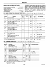
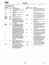
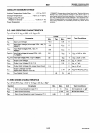
D.C. AND OPERATING CHARACTERISTICS
TA
=
-40°C
to
+8SoC, Vee =
voo
= +5V ±
10%,
Vss=
OV
Limits
Symbol
Parameter
Min. Typ.
Max.
Uhit
Test Conditions
Vil
Input Low Voltage
-0.5
0.6
V
VIH
Input
High
Voltage
(All
Except
XTALl,
XTAL2,
ffESEf)
2.2
Vee
V
VIH1
Input High Voltage (RESET,
Xl,
X2)
3.S
Vee
V
VOL
Output Low Voltage
(BUS,
RD,
WR,
PSEN,
ALE)
0.45
V
IOl
= 1.6
ma
VOl1
Output Low
Voltage
(All Other
Outputs Except
PROG)
0.45 V
IOl
= 1.2
ma
VOL2
Output Low Voltage (PROG)
0.45
V
IOl
= 0.8
rna
VOH
Output High Voltage
(BUS, RD,
WR,
PSEN,
ALE)
2.4
V
IOH
=
-80
j.la
VOH1
Output
High
Voltage
(All
Other Outputs)
2.4
V
IOH
=
-30
j.la
III
Input
Leakage
Current
(n,
INT)
±10
J.l.A
VSS";;VIN";;Vee
IOl
Output
Leakage
Current (Bus,
TO)
(High
Impedance
State)
±10
J.l.A
Vss + 0.45";; VIN
";;Ve
e
100
Power
Down Supply Current
50
mA
TA
= 25°C
loo+lee
Total Supply Current
170
mA
TA
=
2SoC
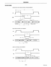
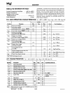
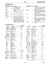
A.C. CHARACTERISTICS T A =
-40
0
C
to
+8S
o
C,
Vee =
Voo
=
+SV
±10%,
Vss
=
OV
Symbol Parameter
Min.
ILL
ALE Pulse
Width
200
t~L
Address Setup
to
ALE
120
tLA
Address
Hold
from ALE
SO
tee
Control Pulse
Width
(PSEN,
RD,
WR)
400
tow
Data Set·Up Before WR
420
two
Data Hold After WR
80
tCY
Cycle Time
2.5
tOR
Data Hold
0
tRO
PSEN,
RD
to
Data In
tAW
Address Setup
to
WR 2:)0
tAD
Address Setup
to
Data In
tAFe
Address Float
to
RD,
PSEN
-40
Not
••
:
1.
8039·6
specifications
are
also valid for 8049/8039 operating at
SMHz.
2.
Control Outputs: C
L
= 80pF
BUS
Outputs: e
L
=
150pF
6-44
Max.
Unit
Conditions
(Note 2)
ns
ns
ns
ns
ns
ns
C
L
=20pF
15.0
,..s
(6 MHz XTAL for
IDS049)
200
ns
400
ns
ns
600
ns
ns
AFN~00737~04