8293
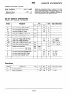
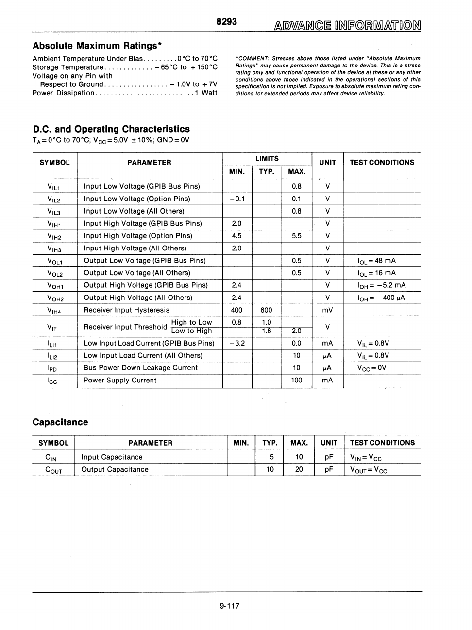
Absolute Maximum Ratings*
Ambient Temperature Under Bias
.........
O·C
to
70·C
Storage Temperature
.............
-
65·C
to
+
150·C
Voltage
011
any Pin
with
Respect
to
Ground
.................
- 1.0V
to
+ 7V
Power
Dissipation
..........................
1 Watt
D.C.
and Operating Characteristics
TA=O·C
to
70·C;
V
cc
=5.0V
±10%;
GND=OV
SYMBOL PARAMETER
VILl
Input Low Voltage (GPIB Bus Pins)
VIL2
Input Low Voltage (Option Pins)
V
IL3
Input Low Voltage (All Others)
V
IH1
Input High Voltage (GpIB Bus Pins)
V
IH2
Input High Voltage (Option Pins)
VIH3
Input High Voltage (All Others)
VO
Ll
Output
Low Voltage (GPIB Bus Pins)
VO
L2
Output
Low Voltage (All Others)
VO
H1
Output
High Voltage (GPIB Bus Pins)
V
OH2
Output
High Voltage (All Others)
V
IH4
Receiver Input Hysteresis
VIT
. High
to
Low
Receiver
Input Threshold Low
to
High
ILI1
Low Input Load Current (GPIB Bus Pins)
IU2
Low Input Load Current (All Others)
Ipo
Bus Power Down Leakage Current
Icc
Power Supply Current
Capacitance
SYMBOL PARAMETER
CIN
Input CapaCitance
COUT
Output
Capacitance
'COMMENT: Stresses
above
those listed under "Absolute Maximum
Ratings" may cause permanent damage to the device.
This
is a stress
rating only and functional operation of
the
device
at
these
or
any other
conditions
above
those Indicated
In
the operational sections
of
this
specification
Is
not Implied. Exposure to absolute maximum rating can·
ditions
10',
extended periods may
affect
device reliability.
LIMITS
UNIT TEST CONDITIONS
MIN. TYP.
MAX.
0.8 V
-0.1
0.1
V
0.8 V
2.0 V
4.5
5.5 V
2.0 V
0.5
V
IOL=48
mA
0.5
V
IOL=
16 mA
2.4
V
IOH=
-5.2
mA
2.4
V
IOH=
-400~
400
600
mV
0.8 1.0
V
1.6
2.0
-3.2
0.0 mA
VIL= 0.8V
10
JJA
V
IL
= 0.8V
10
JJA
Vcc=OV
100
mA
MIN.
TYP.
MAX. UNIT
TEST CONDITIONS
5 10
pF
VIN=V
CC
10
20
pF
VOUT=VCC
9-117


