


8291
B3
- Enable Active Low Interrupt: Setting this bit causes
the polarity
of
the I NT pin
to
be reversed, providing
an
output
signal compatible with Intel's MCS-48'". Interrupt
registers are not affected by this bit.
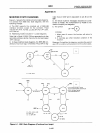
PARALLEL
POLL PROTOCOL
Writing
a 011USP3P2P,
into
the Auxiliary Mode Register
will enable
(U
=
0)
or disable
(U
=
1)
the
8291
for a parallel
poll.
When U =
0,
this command is the
"Ipe"
(local poll
enable) local message as defined in IEEE
488.
The
"S"
bit
is the sense in which the
8291
is enabled; only
if
the
Parallel Poll Flag
("ist"
local message) matches this bit
will
the Parallel Poll Response,
PPR
N
,
be sent true
(Response
=
S~
ist). The
bits
P
3
P
2
P,
specify
which
of
the
eight data lines PPR
N
will
be sent over. Thus,
once
the
8291
has been
configured
for
Parallel Poll, whenever
it
senses both
EOI
and ATN true, it
will
automatically
compare
its
PP
flag
with
the
sense
bit
and send
PPR
N
true or false according
to
the
comparison.
If a PP2' implementation
is
desired, the "Ipe" and
"ist"
local messages are all that are needed. Typically, the user
will configure the
8291
for Parallel Poll immediately after
initialization. During normal operation the
micro-
processor
will
set
or
clear
the
Parallel Poll Flag (ist)
according
to
the device's need
for
service. Consequently
the
8291
will be set up to give the proper response
to
I
DY
(EOI • ATN)
without
directly involving tne micropro-
cessor.
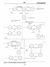
If a PP1' implementation
is
desired, the undefined
command features
of
the
8291
must be used. In
PP1,
the
8291
is
indirectly configured
for
Parallel Poll by the active
controller on the
GPIB. The sequence at the
8291
being
enabled or disabled remotely is as follows:
1.
The
PPC
message is received and is loaded
into
the
Command Pass Through Register as
an
undefined
command. A CPT interrupt
is
sent
to
the microproc-
essor, the handshake is automatically held off.
2.
The microprocessor reads the CPT Register and sends
VSCMD
to
the 8291, releaSing the handshake.
3.
Having received
an
undefined primary command, the
8291
is set up
to
receive
an
undefined secondary com-
mand (the
PPE
or
PPD message). This message is also
received
into
the CPT Register, the handshake is held
off, and the CPT interrupt is generated.
4.
The microprocessor reads
the
PPE
or
PPD
message
and writes the command
into
the Auxiliary Mode
Register (bit
7 should be cleared first). Finally, the
microprocessor sends
VSCMD and the handshake is
released.
'As defined
in
IEEE
Standard 488.
9·95
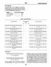
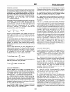
End
of
Sequence
(EaS)
Register
I EC7 I EC6 I EC5 I EC4 I EC3 I EC2
ECl
ECO
I
EOS
REGISTER
The EOS Register and its features
offer
an
alternative
to
the "Send EOI" auxiliary command. A seven
or
eight bit
byte
(ASCII
or
binary) may be placed in the register
to
flag
the end
of
a block or read. The type of EOS byte to be used
is
selected in Auxiliary Register bit
A4.
If the
8291
is
a listener, and the "End on EOS Received"
is
enabled at bit
A2,
then
an
End interrupt
is
generated in the
Interrupt Status 1 Register whenever the byte in the Data-
In
Register matches the byte in the EOS Register.
If the
8291
is
a talker, and the
"Output
EOI on EOS Sent"
is
enabled at bit
A3,
then the EOI line is sent true with the
next data byte whenever the contents
of
the Data
Out
Register match the
EOS
register.
Reset Procedure
The
8291
is reset
to
an
initialization state
either
by a
pulse applied
to
its
Reset pin,
or
by a reset auxiliary
command
(02H
written
into
the
Auxiliary
Command
Register). The
following
conditions
are caused by a
reset
pulse
(or local reset command):
1.
A
"pon"
local message as defined by IEEE 488 is held
true
until
the
initialization
state is released.
2_
The Interrupt Status Registers are cleared (not
Interrupt Enable Registers).
3.
Auxiliary Registers A and B are cleared.
4.
The Serial Poll Mode Register is cleared.
5.
The Parallel Poll Flag is cleared.
6.
The
EOI
bit
in
the
Address Status Register is cleared.
7.
NF
in the Internal Counter is set
to
8 MHz. This set-
ting
causes the longest possible
t,
delay
to
be
generated in
the
Source Handshake
(16
I'sec
for
1
MHz clock).
8.
The rdy local message
is
sent.
The initialization state is released
by an
"immediate
ex-
ecute
pon"
command
(OOH
written
into
the Auxiliary
Command Register).
The suggested
initialization
sequence is:
1.
Apply
a reset pulse or send the reset auxiliary
command.
2.
Set
the
desired initial conditions by
writing
into
the In-
terrupt Enable, Serial Poll Mode, Address Mode,
Address
0/1, and
EOS
Registers. Auxiliary Registers A
and
B,
and the internal counter should also be
initialized.
3.
Send the "immediate execute
pon"
auxiliary command
to
release
the
initialization
state.
4.
If a
PP2
Parallel Poll implementation
is
to
be used the
"Ipe"
local message may be sent, enabling the
8291
for a Parallel Poll Response
on
an
assigned line. (Refer
to
the section on Parallel Poll Protocol.)