SINGLE
COMPONENT
SYSTEM
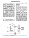
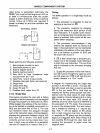
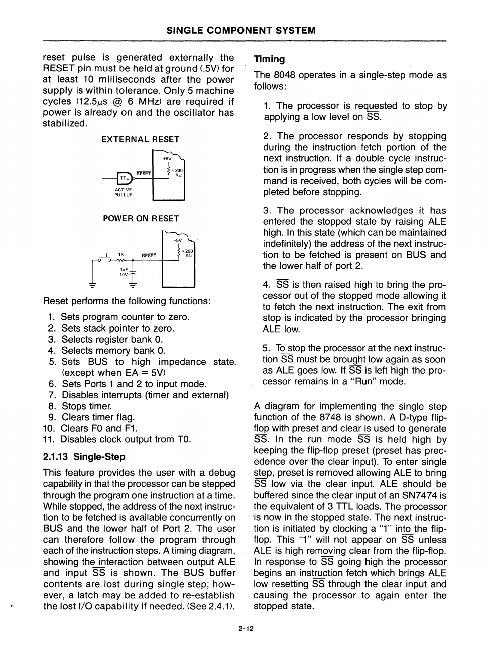
reset pulse is generated externally the
RESET pin must be
held
at
ground
LSV)
for
at least 10 milliseconds after the power
supply
is
within tolerance.
Only
S machine
cycles
(12.SJls
@ 6 MHz) are required
if
power
is
already on and the oscillator has
stabilized.
EXTERNAL
RESET
ACTIVE
PUlLUP
+5V
"=200
Ku
POWE
R ON RESET
--D..-
'K
f
",
lOVI
+5V
""200
K!J
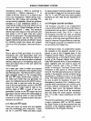
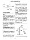
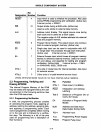
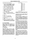
Reset performs the following functions:
1.
Sets program counter to zero.
2.
Sets stack painter to zero.
3.
Selects register bank
O.
4.
Selects memory bank
O.
S.
Sets BUS to high impedance state.
(except when EA
=
SV)
6.
Sets Ports 1 and 2 to input mode.
7.
Disables interrupts (timer and external)
8.
Stops timer.
9.
Clears timer flag.
10.
Clears
FO
and
F1.
11.
Disables clock output from
TO.
2.1.13 Single-Step
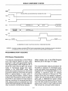
This feature provides the user with a debug
capability
in
that the processor can be stepped
through the program one instruction at a time.
While stopped, the address of the next instruc-
tion to
be
fetched is available concurrently
on
BUS and the lower half of Port
2.
The user
can therefore
follow the program through
each of
the
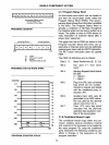
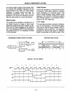
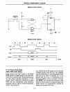
instruction steps. A timing diagram,
showing the interaction between output ALE
and input
SS is shown. The BUS buffer
contents are lost
during
single step;
how-
ever, a latch may be added to re-establish
the
lost
I/O
capability
if
needed. (See 2.4.1).
2·12
Timing
The 8048 operates
in
a single-step mode as
follows:
1.
The processor
is
requested to stop by
applying a
low level
on
SS.
2.
The processor responds by stopping
during the instruction fetch portion of the
next instruction. If a double cycle instruc-
tion
is
in
progress when the single step com-
mand is received, both cycles will be com-
pleted before stopping.
3.
The processor acknowledges it has
entered the stopped state by raising ALE
high.
In
this state (which can be maintained
indefinitely) the address of the next instruc-
tion to be fetched
is
present
on
BUS and
the lower
half of port
2.
4.
SS
is
then raised high to bring the pro-
cessor out of the stopped mode allowing it
to fetch the next instruction. The exit from
stop is indicated by the processor bringing
ALE
low.
S.
To
stop the processor
at
the next instruc-
tion
SS
must be brought low again as soon
as ALE goes
low.
If
SS
is
left high the pro-
cessor remains
in
a "Run" mode.
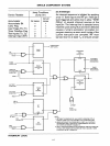
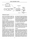
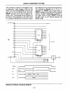
A diagram for implementing the single step
function of the 8748
is
shown. A D-type flip-
flop with preset and clear
is
used to generate
SS.
In
the run mode SS is held high by
keeping the flip-flop preset (preset has
prec-
edence over the clear input).
To
enter single
step, preset
is
removed allowing ALE to bring
SS low via the clear input. ALE should be
buffered since the clear input of
an
SN7474 is
the equivalent of 3 TTL loads. The processor
is
now
in
the stopped state. The next instruc-
tion
is
initiated by clocking a "1" into the flip-
flop. This "1" will not appear
on
SS unless
ALE
is
high removing clear from the flip-flop.
In
response to SS going high the processor
begins
an
instruction fetch which brings ALE
low resetting SS through the clear input and
causing the processor to again enter the
stopped state.


