8272
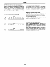
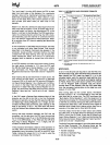
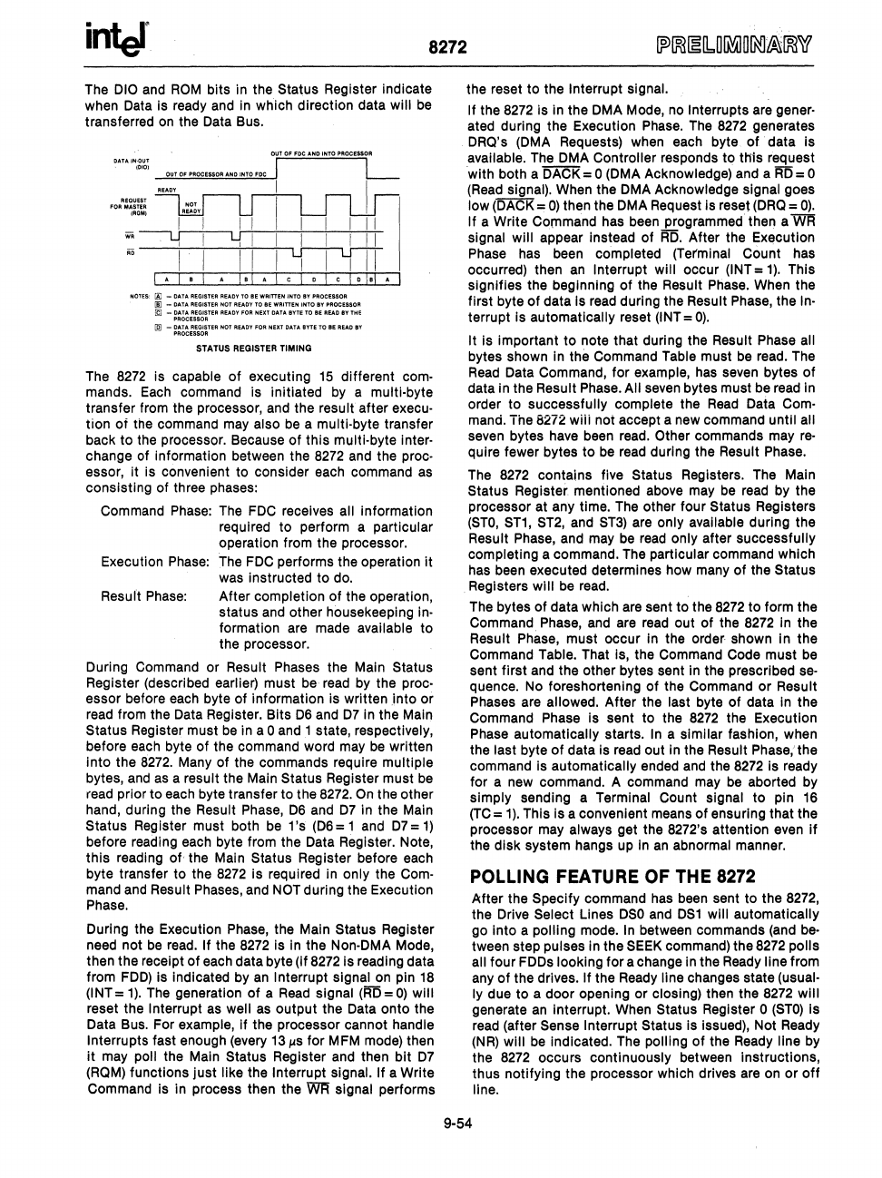
The
010
and
ROM
bits in the Status Register indicate
when
Data
is
ready
and
In
which direction data will
be
transferred
on
the Data Bus.
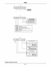
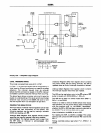
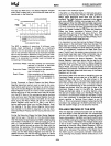
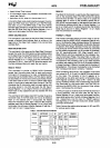
04TAI,.·OUT
1010)
OUT
OF
PROCEnaR
AND
INTO
FDC
I·
NOTES:
@ _
DATA
REOISTER
READY
to
IE
WRITTEN
INTO
BV
PROCE8$OR
I!l -
DATA
REGiStER
HOT
READY
TO
liE
WRITTEN
INTO
IY PAOCUSOR
@ -
OATA
REGISTER
READY
FDA
NEXT
DATA
BYTE
TO
IE
READ
IV
THE
PROCESSOR
[QJ
_
DATA
REGISTER
NOT
READY
FDA
NEXT
DATA
BYTE
TO
III!
READ
BY
PROCESSOR
STATUS
REGISTER
TIMING
• I
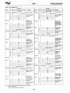
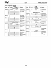
The
8272
Is
capable of executing
15
different
com-
mands.
Each
command is initiated
by
a multi-byte
transfer from the processor,
and
the result after execu-
tion of
the
command
may
also
be
a multi-byte transfer
back to the processor. Because of this multi-byte
Inter-
change of information between the
8272
and the proc-
essor,
It is convenient to consider each command
as
consisting of three phases:
Command
Phase:
The
FDC
receives all Information
required to perform a particular
operation from the processor.
Execution
Phase:
The
FDC
performs the operation It
was
Instructed to
do.
Resuft
Phase:
After completion
of
the operation,
status
and
other housekeeping
In-
formation
are
made available to
the processor.
During Command or Result Phases the Main
Status
Register (described earlier) must
be
read
by the proc-
essor before
each
byte of information
Is
written
into
or
read
from the
Data
Register. Bits 06
and
07 in the Main
Status Register must
be
In
a 0 and
_1
state, respectively,
before
each
byte of the command word
may
be
written
Into the
8272.
Many of the commands require multiple
bytes,
and
as
a result the Main Status Register must
be
read
prior to each byte transfer to the
8272.
On
the other
hand, during the Result
Phase,
06 and 07
In
the Main
Status Register must both
be
1's
(06=
1 and
07=
1)
before reading
each
byte from the
Data
Register. Note,
this reading
of-
the Main Status Register before
each
byte transfer to the
8272
is required in only the
Com-
mand
and
Result Phases,
and
NOT
during the Execution
Phase.
During the Execution
Phase,
the Main Status Register
need
not
be
read.
If the
8272
Is
in the Non-DMA Mode,
then the receipt
of
each data byte (If
8272
Is reading data
from
FDD)
is indicated by
an
Interrupt signal on pin
18
(lNT =
1).
The generation
of
a
Read
signal
(im
=
0)
will
reset the
Interrupt
as
well
as
output the Data onto the
Data
Bus.
For example, If the processor cannot handle
Interrupts fast enough
(every
13/o1s
for
MFM
mode)
then
It
may
poll the Main Status Register and then bit 07
(ROM)
functions just like the Interrupt signal. If a Write
Command
Is
In process then the
WFf
Signal performs
the reset to the
Interrupt signal.
If the
8272
Is
in the DMA Mode, no Interrupts
are
gener-
ated during the Execution
Phase.
The
8272
generates
ORa's
(DMA
Requests)
when
each byte
of
data Is
available. The DMA Controller responds to this request
'with both a DACK = 0
(DMA
Acknowledge) and a
RD
= 0
(Read
signal). When the
DMA
Acknowledge signal goes
low
(DACK
=
0)
then the
DMA
Req
uest
Is
reset
(ORO
=
0).
If a Write
COmmand
has
been programmed- then a
WR
Signal will appear Instead of
RD.
After the EXf!cution
Phase
has
been
completed (Terminal Count
has
occurred) then
an
Interrupt will occur (INT =
1).
This
signifies the beginning
of
the Result
Phase.
When
the
first byte
of
data
Is
read
during the Result
Phase,
the
In-
terrupt
Is
automatically reset
(INT
=
0).
It is important to note that during the Result Phase all
bytes shown
In
the Command Table must
be
read.
The
Read
Data Command, for example,
has
seven bytes of
data in the Result
Phase.
All
seven
bytes must
be
read
In
order to successfully complete the
Read
Data
Com-
mand. The
8272
will not accept a new command until all
seven
bytes
have
been
read.
Other commands
may
re-
quire fewer bytes to
be
read
during the Result
Phase.
The
8272
contains five Status Registers.
The
Main
Status Register mentioned above
may
be
read
by the
processor at any time.
The
other four Status Registers
(STO,
ST1, ST2,
and
ST3)
are
only available during the
Result
Phase,
and
may
be
read
only after successfully
completing a command.
The
particular command which
has
been
executed determines how many
of
the Status
_
Registers will
be
read.
The bytes of data which
are
sent to the
8272
to form the
Command
Phase,
and
are
read
out of the
8272
in the
Result Phase, must occur
In
the
order,
shown In the
Command Table. That
Is, the Command Code must
be
sent first and the other bytes sent
In
the prescribed
se-
quence.
No
foreshortening
of
the Command or Result
Phases
are
allowed. After the last byte
of
data
In
the
Command Phase is sent to the
8272
the Execution
Phase
automatically starts. In a similar fashion, when
the last byte
of
data is
read
out
In
the Result Phase;the
command
Is
automatically ended
and
the
8272
Is
ready
for a new command. A command
may
be
aborted by
simply sending a Terminal
Count signal to pin
16
(TC
=
1).
This
Is
a convenient means
of
ensuring that the
processor
may
always get the 8272's attention
even
If
the disk system hangs
up
In
an
abnormal manner.
POLLING FEATURE OF THE 8272
After the Specify command
has
been
sent to the
8272,
the Drive Select Lines
DSO
and
DS1
will automatically
go into a polling mode.
In
between commands
(and
be-
tween step pulses in the
SEEK
command) the
8272
polls
all
four FDDs looking for a change
In
the
Ready
line from
any
of
the drives. If the
Ready
line changes state (usual-
ly due to a door opening or closing) then the
8272
will
generate
an
Interrupt.
When
Status Register 0
(STO)
Is
read
(after Sense Interrupt Status is Issued), Not
Ready
(NR)
will
be
indicated. The polling
of
the
Ready
line
by
the
8272
occurs continuously between instructions,
thus notifying the processor which drives
are
on or
off
line.
9-54


