8253/8253·5
Read
Operations
In
most
counter
applications
it
becomes
necessary
to
read
the
value
of
the
count
in
progress
and
make
a
computational
decision
based
on
this
quantity.
Event
counters
are
probably
the
most
common
application
that
uses
this
function.
The
8253
contains
logic
that
will
allow
the
programmer
to
easily
read the
contents
of any
of
the
three
counters
without
disturbing
the
actual
count
in
progress.
There
are
two
methods
that
the
programmer
can use
to
read
the
value
of
the
counters.
The
first
method
involves
the
use
of
Simple
1/0
read
operations
of
the
selected
counter.
By
controlling
the
AO,
A I
inputs
to
the
8253
the
programmer
can
select
the
counter
to
be read
(remember
that
no
read
operation
of
the
mode
register
is
allowed
AO,
AI-II).
The
only
requirement
with
this
method
is
that
in
order
to
assure a
stable
count
reading
the
actual
operation
of
the
selected
counter
must
!:!f
inhibited
either
by
controlling
the
Gate
Input
or
by
external
logic
that
Inhibits
the
clock
Input.
The
corotents of the
counter
selected
will
be
available
as
follows:
first
I/O
Read
contains
the
least
significant
byte
(lSB).
second
1/0
Read
contains
the
most
significant
byte
(MSB).
Due
to
the
internal
logic
of
the 8253 it is
absolutely
necessary
to
complete
the
entire
reading
procedure.
If
two
bytes are
programmed
to
be read then
two
bytes
must
be
read
before
any
loading
WR
command
can be sent
to
the
same
counter.
3MHz
ClK
8085
2
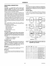
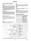
Read
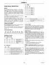
Operation Chart
Al
AD
RD
a
a
a
Read
Counter No, a
a
1
a
Read
Counter No. I
1 a a
Read
Counter
No.2
1
1
0 Illegal
Reading While Counting
I n
order
for
the
programmer
to read
the
contents
of any
counter
without
effecting
or
disturbing
the
counting
operation
the 8253 has speCial
internal
logiC
that
can be
accessed
uSing
simple
WR
commands
to
the
MODE
register. BaSically.
when
the
programmer
wishes
to
read
the
contents
of a selected
counter
"on
the
fly"
he loads the
MODE
register
with
a special
code
which
latches
the
present
count
value
Into
a
storage
register
so that Its
contents
contain
an accurate,
stable
quantity.
The
programmer
then
Issues a
normal
read
command
to
the
selected
counter
and the
contents
of
the
latched
register
IS
available
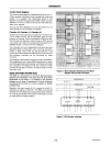
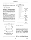
MODE Register
for
Latching Count
AD,
A1
11
SCI,SCO-
speCify
counter
to be
latched.
05,04
X
00
designates
counter
latching
operation.
don't
care.
The
same
limitation
applies
to
this
mode
of
reading
the
counter
as
the
previous
method.
That
is,
it
is
mandatory
to
complete
the
entire
read
operation
as
programmed,
This
command
has
no
effect
on
the
counter's
mode.
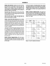
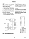
• 1,5MHz
ClK
8253-5
"If
an
8085 clock output is to drive
an
8253·5 clock input,
it
must be reduced to 2 MHz or less,
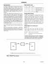
Figure 8. MCS-8S™ Clock Interface"
9-13
AFN-00745A-08


