


8259A
PROGRAMMING
THE
8259A
The
8259A
accepts two types
01
command words gener·
ated
by
the
CPU:
1.
Initialization Command Words (lCWs): Belore normal
operation can begin. each
8259A
in the system must
be brought to a starting point -
by
a sequence
01
2 to
4 bytes timed
by
imi pulses. This sequence is
described in Figure
1.
2.
Operation Command Words (OCWs): These
are
the
command words which command the 8259A to
oper·
ate in various interrupt modes. These modes
are:
a.
Fully nested mode
b.
Rotating priority mode
c.
Special mask mode
d.
Polled mode
The
OCWs
can
be
written into the
8259A
anytime alter
initialization.
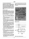
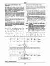
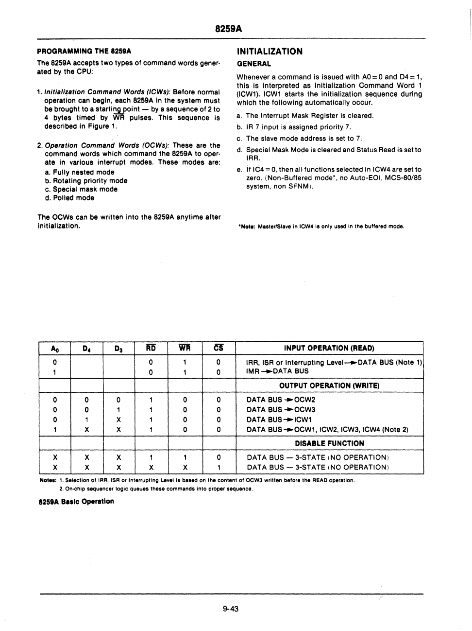
Ao
D4
D3
RD
WR
CS
0
0
1
0
1 0 1 0
0 0 0
1 0 0
0 0
1 1
0 0
0
1
X 1 0
0
1
X X 1 0 0
X X X 1
1
0
X X X X X 1
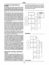
INITIALIZATION
GENERAL
Whenever a command is issued with
AO
= 0 and
D4
=
1,
this is interpreted
as
Initialization Command Word 1
(ICW1).
ICW1
starts the initialization sequence during
which the following automatically occur.
a.
The Interrupt
Mask
Register
is
cleared.
b.
IR
7 input
is
assigned priority
7.
c.
The slave mode address
is
set
to
7.
d.
Special
Mask
Mode
is
cleared
and
Status
Read
is
set to
IRR.
e.
If IC4 =
O.
then all functions selected in
ICW4
are
set to
zero. (Non-Buffered mode'.
no
Auto-EOI. MCS-80/85
system. non SFNM).
'Nol.:
Master/Slave In ICW4 Is only used in the buffered mode.
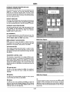
INPUT
OPERATION
(READ)
IRR.
ISR
or Interrupting Level-+-DATA
BUS
(Note
1)
IMR
.--DATA
BUS
OUTPUT
OPERATION
(WRITE)
DATA
BUS
--OCW2
DATA
BUS
--OCW3
DATA
BUS
....
ICW1
DATA
BUS
....
OCW1.ICW2.ICW3.ICW4 (Note
2)
DISABLE FUNCTION
DATA
BUS
- 3-STATE
(NO
OPERATION)
DATA
BUS
- 3-STATE
(NO
OPERATION)
Nol."
t.
Selection
of
IRR. ISR
or
Interrupting Level Is based on the content of OCW3 written before the
READ
operation.
2.
On-chip sequencer
logic
queues these commands
into
proper sequence.
8259A
Ba.le Operation
9-43