8155/8156/8155-2/8156-2
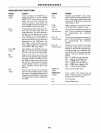
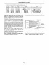
TABLE
1.
TABLE OF PORT CONTROL ASSIGNMENT.
Pin
ALT
1
ALT
2
ALT
3
pca
input
Port
Output
Port A INTR (Port A Interrupt)
PC1
Input Port
Output
Port
A BF (Port A Buffer Full)
PC2
Input Port
Output
Port A STB (Port A Strobe)
PC3
Input Port
Output
Port
PC4
Input Port
Output
Port
PC5
Input Port
Output
Port
Note in the diagram that when the
1/0
ports are
pro-
grammed to be
output
ports. the contents
of
the output
ports can still be read by a READ operation when appro-
priatelyaddressed.
Output Port
Output Port
Output Port
ALT4
A INTR (Port A Interrupt)
A
BF
(Port A Buffer Full)
A STB (Port A Strobe)
B INTR (Port B Interrupt)
B
BF
(port B Buffer Full)
B
STB (Port B Strobe)
TO
8085 RST INP
UT
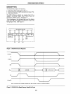
The outputs
of
the 8155/8156 are "glitch-free" meaning
that you can write a
"1" to a
bit
position that was previ-
ously
"1" and the level at the
output
pin will
not
change.
PORT A
OUTPUT PORT A r
A
INTA
(SIGNALS
DATA
RECEIVED)
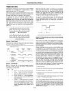
Note also that the
output
latch is cleared when the port
enters the
input
mode. The
output
latch cannot
be
loaded
by
writing to the port if the port is in the
input
mode. The
result is that each time a port mode is changed from
input
to
output, the output pins will
go
low. When the 8155/56
is
RESET, the output latches are all cleared and al13 ports
enter the
input
mode.
....
.,
..
1
,,>
'",,,,,,m
"'~,
I A
srB
(ACKNOWL
DATA
RECEIVED)
PORT C B STS
(LOADS
PORT B
LATCH)
B SF (SIGNALS BUFFER IS
FULL)
B
INTR
(SIGNALS
BUFFER r
}
TO/FROM
PERIPHERAL
INTERFACE
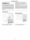
When in the AL T 1
or
AL T 2 modes, the bits
of
PORT C
are structured like the diagram above in the simple
input
or
output
mode, respectively.
Reading from
an
input
port with nothing connected to the
pins will provide unpredictable results.
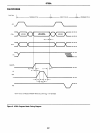
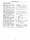
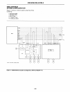
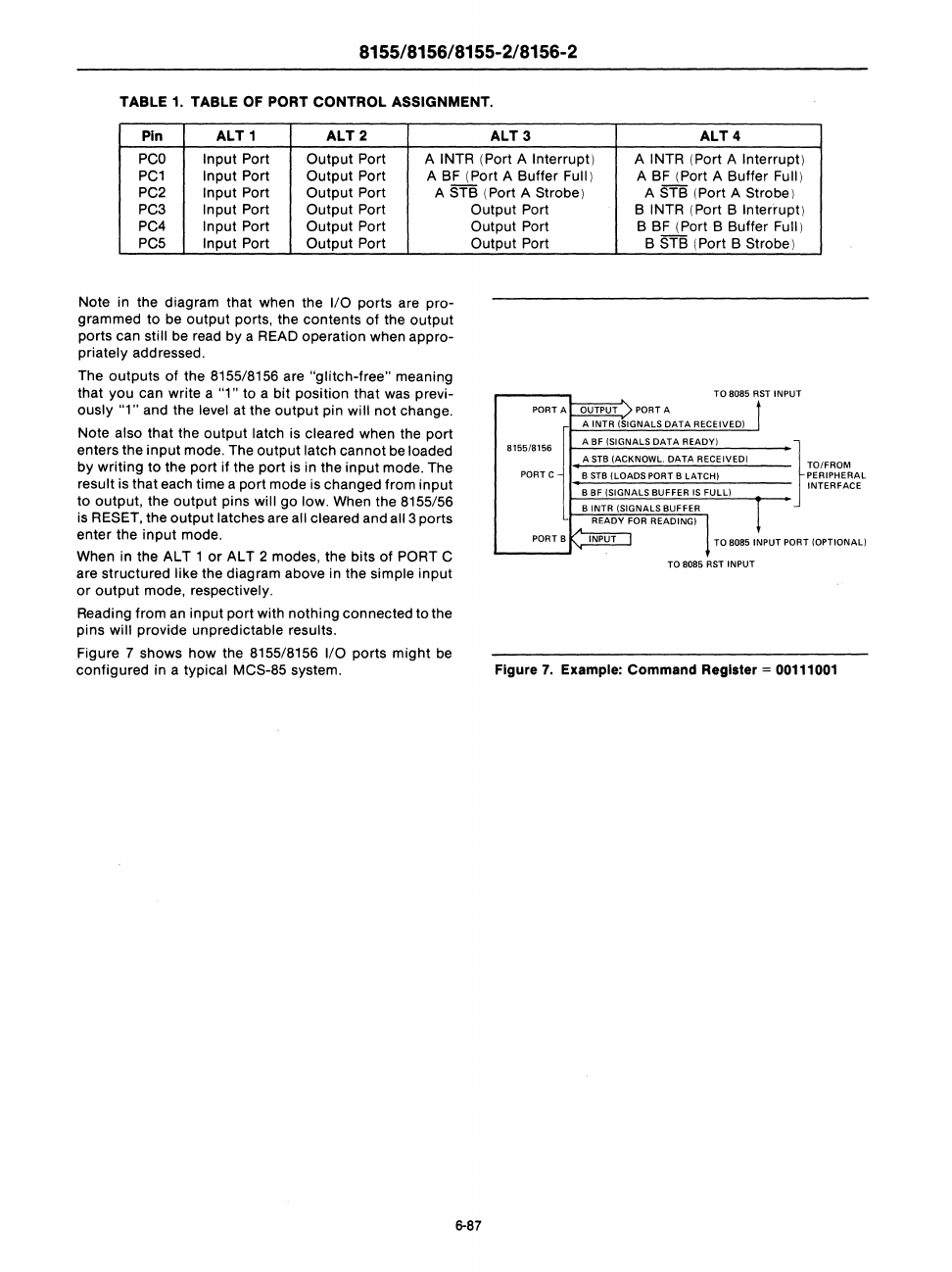
Figure 7 shows
how
the 8155/8156
1/0
ports
might
be
configured in a typical
MCS-85 system.
6-87
READY
FOR
READINGI
1
PORT B INPUT TO 8085 INPUT P
ORT
(OPTIONAL)
TO 8085 RST INPUT
Figure
7.
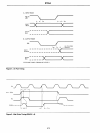
Example: Command Register = 00111001


