inter
8272
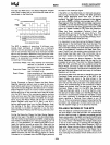
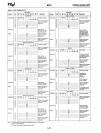
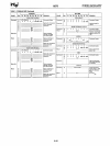
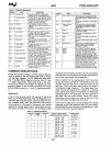
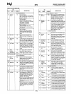
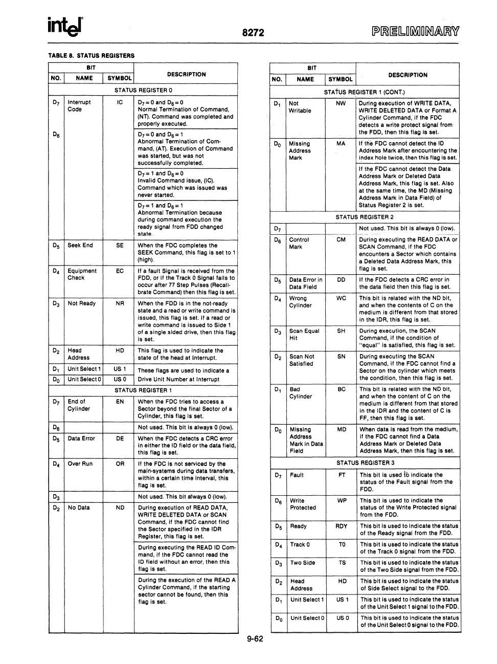
TABLE 8. STATUS REGISTERS
BIT
BIT
NO.
NAME SYMBOL
DESCRIPTION
SYMBOL
DESCRIPTION
NO.
NAME
STATUS REGISTER 0
STAtUS
RE.GISTER
, (CO
NT.)
0
7
Interrupt
IC
D7~Oand
Ds~O
Code Normal Termination
of
Command,
0,
Not
NW During
execution
of
WRITE DATA,
Writable
WRITE DELETED DATA or Format A
(NT).
Command was completed and
Cylinder Command, If the FDC
properly executed.
detects
a
write
protect signal from
Os
07=0
and
Ds='
the
FDD, then
this
flag Is set.
Abnormal Termination of
Com·
mand,
(AT).
Execution
of
Command
was started, but was not
successfully
completed.
Do
MISSing MA
If
tlie
FDC cannot detect the
10
Address
Address Mark
after
encountering the
Mark
Index hole twice, then
this
flag is set.
0
7
='
and
Ds=O
Invalid Command issue,
(I
C).
Command which was issued was
never started.
If
the FOC cannot
detect
the Data
Address
Mark or Deleted Data
Address Mark,
this
flag Is set. Also
at the
sam.e
time, the MD (Missing
Address Mark in Data
Field)
of
0
7
='
and
Ds='
Status Register 2 is set.
Abnormal Termination because
during
command execution the
STATUS REGISTER 2
ready
signal from FDD changed
state.
0
7
Not
used. This bit is always 0 (low).
----
--~
0
5
Seek End
SE
When the FDC completes the
0
6
Control
CM
During
executing
the READ DATA or
Mark
SCAN Command,
if
the FOC
SEEK
Command,
this
flag Is set to ,
encounters a
Sector which contains
(high).
a
Deleted Data Address Mark,
this
0
4
Equipment
EC
If
a fault Signal is received from the
flag is set.
Check
FDD, or If the Track 0 Signal fails to
occur
after
77
Step Pulses (Recali·
brate Command) then
this
flag Is set.
0
5
Data Error in
00
If the FOC
detects
a CRC error
In
Data Field
the data field then
this
flag is set.
0
3
Not
Ready
NR
When the FDD
is
in the not· ready
state and a read or write command is
0
4
Wrong WC
This
bit
is related
with
the
NO
bit,
Cylinder
and when the
contents
of
C on the
medium is different from that stored
issued,
this
flag Is set. If a read or
write
command is issued
to
Side 1
In
the lOR,
this
flag is set.
of
a single sided drive, then
this
flag
is set.
0
3
Scan
Equal
SH
During execution, the SCAN
Hit
Command,
if
the
condition
of
O
2
Head HD This flag is used to Indicate the
Address state
of
the head at Interrupt.
"equal"
is
satiSfied,
this
flag is set.
O
2
Scan
Not
SN
During
executing
the SCAN
0,
Unit
Select'
US,
These flags are used
to
indicate a
Satisfied
Command, If the FDC cannot find a
Sector on the cylinder which meets
Do
Unit SelectO
usa
Drive Unit Number at Interrupt
the condition, then
this
flag is set.
STATUS
REGISTER'
0,
Bad
BC
This
bit
is related
with
the
NO
bit,
0
7
End of
EN
When the FDC tries to access a
Cylinder and when the content of C
on
the
medium
is
different from that stored
Cylinder
Sector
beyond the final Sector
of
a
In
the lOR and the content
of
C
is
Cylinder,
this
flag Is set.
FF, then
this
flag is set.
Os
Not
used. This bit
is
always 0 (low).
Do
Missing MD
When
data
Is read from the medium,
05
Data
Erwr
DE
When the FDC
detects
a CRC error
In
either the
10
field or the data field,
this
flag Is set.
Address
If the FOC cannot find a Data
Mark
In Data
Address Mark or
Deleted Data
Field
Address Mark, then
this
flag Is set.
0
4
Over
Run
OR
If
the FDC Is not serviced by the
STATUS REGISTER 3
main-systems during data transfers,
within
a certain
time
Interval,
this
flag Is set.
0
7
Fault
FT
This
bit
Is used
I"
indicate the
status
of
the
Fault signal from the
FDO.
0
3
Not
used. This
bit
always 0 (low).
Os
Write WP
This
bit
Is used
to
indicate the
O
2
No Data
NO
During execution
of
READ DATA, Protected
status
of
the
Write
Protected Signal
WRITE
DELETED DATA
or
SCAN from
the
FDO.
Command, If the FDC cannot find
the
Sector specified in the lOR
Register,
this
flag is set.
0
5
Ready
ROY
This
bit
is
used to indicate the status
of
the Ready signal from the FDD.
During executing the READ
10
Com·
mand,
if
the FDC cannot read
the
0
4
Track 0
TO
This
bit
is
used to indicate the status
of
the Track 0 signal from the
FOO.
10
field
without
an error, then
this
flag is set.
0
3
Two Side
TS
This
bit
is
used to indicate the status
of
the Two Side signal from the FDD.
During the execution
of
the READ A
Cylinder Command,
if
the starting
02
Head
HO
This
bit
is
used
to
indicate the status
Address
of
Side
Select
signal to the FDD.
sector
cannot be found, then
this
flag is set.
0,
Unit
Select'
US,
This
bit
is
used to Indicate the status
of
the
Unit
Select'
signal
tothe
FDD.
Do
Unit Select 0
usa
This
bit
is
used to indicate the status
of
the Unit Select 0 signal
tothe
FDD.
9-62


