8291
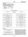
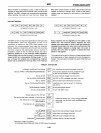
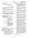
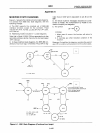
Auxiliary Mode Register
I
CNT21
CNT1 I CNTO I
COM41
COM31
COM21
COM'
I
COMO
I
AUX
MODE (5W)
CNTO-2:CONTROL BITS
COMO-4:COMMAND BITS
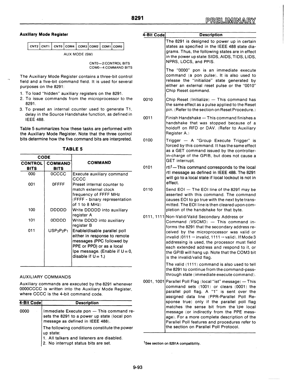
The Auxiliary Mode Register contains a three-bit control
field and a five-bit command field.
It is used for several
purposes on the 8291:
1.
To load
"hidden"
auxiliary registers on the 8291.
2.
To
issue commands from the microprocessor to the
8291.
3.
To preset
an
internal counter used to generate T1,
delay in the Source Handshake function,
as
defined in
IEEE 488.
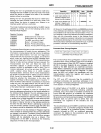
Table 5 summarizes how these tasks are performed with
the Auxiliary Mode Register. Note that the three control
bits determine how the five command bits are interpreted.
TABLE
5
CODE
CONTROL COMMAND
BITS BITS
000
OCCCC
001
OFFFF
COMMAND
Execute auxiliary command
ccee
Preset internal counter to
match external clock
frequency
of
FFFF
MHz
(FFFF - binary representation
of
1
to
8 MHz)
100 DDDDD Write DDDDD into auxiliary
register A
101
ODDDD Write DDDD into auxiliary
register B
011
USP3P2Pi Enable/disable parallel poll
AUXILIARY COMMANDS
either in response
to
remote
messages
(PPC
followed by
PPE
or
PPD)
or
as a local
Ipe
message. (Enable
if
U =
0,
disable
if
U =
1.)
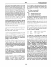
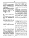
Auxiliary commands are executed by the
8291
whenever
OOOOCCCC
is written
into
the Auxiliary' Mode Register,
where
ecce
is the
4-bit
command code.
4-Blt Code
Descri
tion
0000 Immediate Execute pon - This command re-
. sets the
8291
to
a
power
up state (local pon
.'
message as defined in IEEE 488).
The
following conditions constitute the power
up state:
1.
All talkers and listeners are disabled.
2.
No
interrupt status bits are set.
9-93
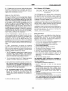
4-Blt Code Description
The
8291
is designed
to
power up in certain
states
as
spec,ified
in
the IEEE 488 state dia-
grams. Thus, the
following states are in effect
in the power upstate: SIDS, AIDS, TIDS, LIDS,
NPRS, LOeS, and PPIS.
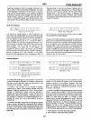
The "0000" pon is an immediate execute
command
(a
pon pulse). It is also used to
release the "initialize" state generated by
either
an
external reset pulse
or
the "0010"
Chip
Reset.command.
0010 Chip Reset (Initialize) - This command has
the same effect
as
a pulse applied
to
the Reset
pin. (Refer to the section on Reset Procedure.)
0011
Finish Handshake -
This
command finishes a
handshake that
was
stopped because
of
a
holdoff
on RFD
or
DAV. (Refer
to
Auxiliary
Register A.)
0100 Trigger - A
"Group
Execute Trigger"
is
forced by this command. It has the same effect
as
a GET command issued by the controller-
in-charge
of
the GPIB, but does not cause a
GET interrupt.
0101
rtl
t
-
This command corresponds
to
the local
rtl message as defined in
IEEE 488. The
8291
will
go
to a local state
if
local lockout
is
not in
effect.
0110 Send EOI - The
EOI
line
of
the
8291
may be
asserted with this command. The command
causes
EOI
to
go
true with the next byte trans-
mitted. The
EOlline
is then cleared upon
com-
pletion
of
the handshake
for
that byte.
0111,
1111
Non-Valid/Valid Secondary Address or
Command
(VSCMD) -
This
command in-
forms the
8291
that the secondary address re-
ceived by the microprocessor was valid
or
invalid
(0111
- invalid,
1111
- valid). If
Mode3
addressing is used, the processor must field
each extended address and respond to it,
or
the GPIB will hang
up.
Note that the COM3 bit
is the invalid/valid flag.
The valid (1111) command is also used to
tell
the
8291
to continue from the command-pass-
through state (immediate execute command).
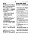
0001,
1001
Parallel Poll Flag (local
"ist"
message) - This
command sets (1001)
or
clears (0001) the
parallel poll flag. A
"1"
is sent over the
assigned data line (PPR-Parallel Poll Re-
sponse true)
only
if the parallel poll flag
matches the sense
bit
from
the'lpe
local
message (or indirectly from the
PPE
mess-
age). For a more complete description
of
the
Parallel Poll features and procedures refer
to
the
section on ParaHel Poll Protocol.
ISee section on 8291A compatibility.


