


821618226
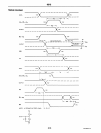
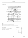
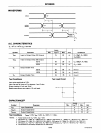
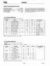
WAVEFORMS
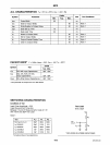
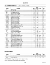
A.C.
CHARACTERISTICS
Limits
Symbol
Parameter Min.
Typ.ll)
Max.
U"nit
Conditions
TpOl
Input
to
Output
Delay DO
Outputs
15
25
ns
CL=30pF,R,=300n
R2=600n
Tp02
Input
to
Output
Delay
DB
Outputs
8216
19
30
ns
"
C
L
=300pF,
R 1
=90n
8226
Te
Output
Enable Time
8216
8226
TO
Output
Disable Time
T.st
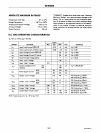
Conditions:
Input
pulse amplitude
of
2.5V.
I
nput
rise and fall times
of
5 ns between 1 and 2 volts.
Output
loading
is
5 mA and
10
pF.
Speed
measurements are made
at
1.5
volt levels.
CAPACITANCEIII
Symbol
Parameter
CIN
Input
Capacitance
COUT!
Output
Capacitance
CoUT2
Output
Capacitance
16
25
ns
R2
=
180n
42
65
ns
(Note
2)
36
54
ns
(Note
3)
16
35
ns
(Note
4)
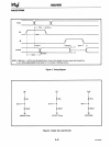
Test
Load
Circuit
",
OUT
O---T------+
",
Limits
Min.
Typ.(1)
Max.
4
8
6
10
13 18
Test
Conditions
VBIAS
= 2.5V, Vee = 5.0V,
TA
= 25°C, f = 1 MHz.
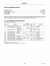
NOTes:
1.
Typical
values
are for
TA
•
25°C,
VCC
=
6.0V.
Unit
pF
pF
pF
2.
00
Outputs.
CL·
3OpF,
R, ·300110
K.!l,
R2·
180/1K.!l;
08
Outputs.
CL
= 300pF, R, =
90110
KO.
R2
= 180/1
KO.
3.
00
Outputs,
CL
=
3OpF,
R,
• 3OO/10K.!l,
R2
=
6OOI1K;
DB
Outputs,
CL
=300pF, R, =90/l0KO, R2= 180/1
KO.
4.
00
Outputs.
CL·
6pF,
R,
= 3OO/10KO,
R2·
60011
KO;
DB
Outputs,
CL
= 6pF, R, =
90/10
KO,
R2
= 180/1
KO.
S.
This
parameter i. periodically
sampled
and not
100%
tested.
8-40
AFN-«l733A-03