


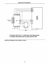
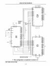

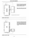
ADDING 8 INPUT LINES
+5V
GND
C-l.
L
Vee
VOD
Vss
Pl0
27
2
-
XTAL
1
Pl1 28
P12 29
3
P13
30
-
XTAL
2
P14
31
P15
32
4
P16
33
-
RESET
P17 34
7
P20
21
-
EA
P21
22
8049
P22
23
P23
24
-ss
8048
P24
35
8748
P25
36
P26
37
P27
38
1
_TO
DBO
12
39
081
13
_Tl
D82
14
6
DB3 15
-
iNT
DB4
16
DB5
17
DB6 18
DB?
19
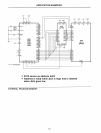
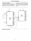
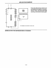
ADDING 8 OUTPUT LINES
APPLICATION EXAMPLES
CLR
74LS259
0
1161
A
G
08
07
06
05
04
03
02
01
5·14
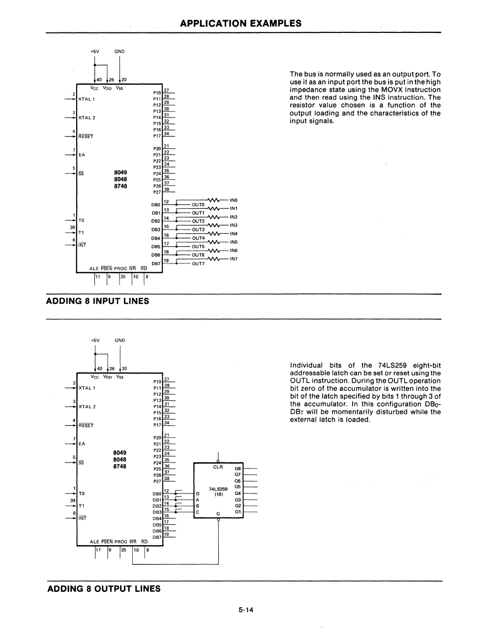
The bus is
normally
used as
an
output
port. To
use it as an
input
port the bus is put in the high
impedance state using the MOVX instruction
and then read using the
INS instruction. The
resistor value chosen is a function
of
the
output
loading and the characteristics
of
the
input
signals.
Individual bits
of
the 74LS259 eight-bit
addressable latch can be set
or
reset using the
OUTL instruction. During the OUTL operation
bit zero
of
the
accumulator
is
written into the
bit
of
the latch specified by bits 1 through 3 of
the accumulator.
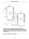
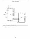
In this configuration DSo-
DS7
will be momentarily disturbed while the
external latch
is
loaded.