


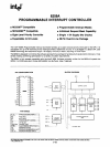
8259A
INTERRUPT
SEQUENCE
OUTPUTS
MCS·80/85 SYSTEM
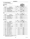
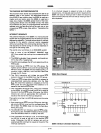
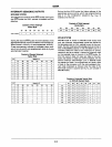
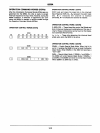
This sequence
is
timed by three INTA pulses. During the
first
iiifi'A
pulse the CALL opcode
is
enabled
onto
the
data bus.
-
Content
of
First
Interrupt
Vector Byte
D7
D8 D5
D4 D3
D2
Dl
DO
CALLCODE
~1_l
_________
0
____
0
____________
0
____
l~1
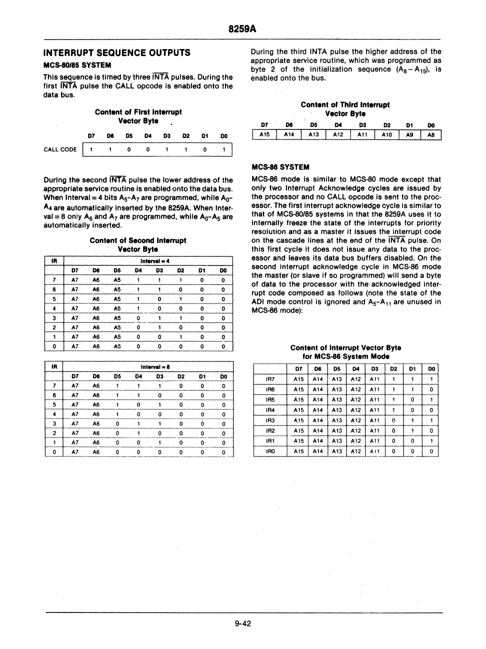
During the second INTA pulse the lower address
of
the
appropriate service routine
is
enabled
onto
the data bus.
When
Interval = 4
bits
A5-A7 are programmed, while Ao-
A4
are automatically inserted by the 8259A. When Inter·
val
= 8 only
A6
and
A7
are programmed, while Ao-A5 are
automatically inserted.
IR
7
6
5
4
3
2
1
0
IA
D7
A7
A7
A7
A7
A7
A7
A7
A7
Content
of
Second Interrupt
Vector Byte
Intervll-4
D8
D5
04
D3
02
A6 A5
1
1
1
A6 A5
1 1 0
A6
A5
1
0
1
A6 A5
1 0 0
A6 A5
0 1 1
A6
A5
0 1 0
A6
A5
0
0
1
A6
A5
0 0 0
Interval
=8
Dl
DO
0 0
0 0
0 0
0 0
0 0
0
0
0 0
0
0
o7
____
o_6
_____
D_5
____
o_4
____
o_3
____
D_2_~_0_1
__
~0~~_
7
~~
____
A~6~
____
~
___
~
__
~
___
~O~
__
~O
____
O~
6
A7
__
A~6
_____
~
__
~
__
~O
__
~O:
____
~O
____
~
~~~A-7----A~6--------0~----~--~O----O~--~O~
4
A7 A6
0 0 0 0
c--------------
3
A7 A6
0 1 0 0
o.~
2
A7
A6
0 1 0 0 0 0
---
--------
------~--~-.-
1--1
__
~7
__
~6
___
~
__
Cl...
___
~
____
O"
____
~
__
~
o
A7
A6
0 0 0 0 0 0
9-42
During the third
INTApuise
the higher address
of
the
appropriate service routine, which was programmed as
byte 2
of
the initialization sequence (As - A
1
sl,
is
enabled
onto
the bus.
07 06
A15
A14
Content
of
Third Interrupt
Vector Byte
05
D4
03
02
A13
A12
All
Al0
01
DO
A9
AS
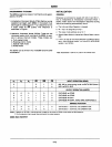
MCS·8S SYSTEM
MCS·86
mode
is
similar
to
MCS·80 mode except that
only
two
Interrupt Acknowledge cycles are issued by
the processor and
no
CALL opcode
is
sent to the proc·
essor. The
first
interrupt acknowledge cycle
is
similar
to
that
of
MCS-80/85 systems in that the 8259A uses
it
to
internally freeze the state
of
the interrupts
for
priority
resoiuiion ana as a master
it
issues the interrupt code
on the cascade lines at the end
of
the INTA pulse.
On
this
first
cycle it does not issue any data to the proc-
essor and leaves
its
data bus buffers disabled.
On
the
second interrupt acknowledge cycle in
MCS·86 mode
the master (or slave
if
so programmed) will send a byte
of
data
to
the processor
with
the acknowledged inter·
rupt code composed as
follows
(note the state
of
the
ADI mode control
is
ignored and
A5-All
are unused in
MCS-86 mode):
IR7
IR6
IR5
IR4
IR3
IR2
IRI
IRO
Content
of
Interrupt Vector Byte
for
MCS·86 System Mode
07
08
05 04 03
02
01
00
A15 A14
A13
A12
All
1 1 1
A15
A14
A13
A12
All
1 1
0
A15 A14 A13
A12
All
1
0 1
A15 A14
A13
A12
All
1
0 0
'115
A14
A13
A12
Al_~
1
1
A15 A14
A13
A12
'Ill
0
1
0
A15
A14
A13 A12
All
0
0
1
A15
A14
A13 A12
All
0 0 0
~
___
L....--
__
~_