


HĆ18 800 Series Operator's Manual
9. Open the hydraulic walls and lock the counterbalance hinges.
10. Tighten the two screws in the alignment bosses on the CO-ox module chassis
to the chassis receptacles of the 800 base model.
11. Install the two plugs retained from the 800 base model to the right side wall.
Ensure that the new adhesive dots are in place.
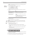
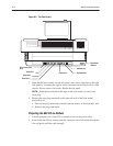
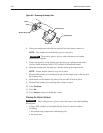
12. Install the communications cable connectors between the CO-ox module and
the 800 base model to the CO-ox communications ports shown in Figure H-5.
Tighten the connector screws.
13. Ensure that the CO-ox module PC boards are firmly seated.
14. Ensure the the lamp is aligned correctly in the keyway and firmly seated in the
housing retainer.
15. Apply the new instrument label over the existing instrument label.
Installing the Sample Connector to the Fluid Path
1. Access the preheater on the measurement module and disconnect the sample
tubing.
2. Remove the sample connector:
a. Remove the screw, located in the front of the preheater block, that attaches
the sample tee adaptor and retain.
b. Remove the sample tee adaptor.
Ensure that the gasket around the tube is in place and does not slip off the
end of the tube.
CAUTION:ĄĂOvertightening the screw can damage the sample tee adaptor.
3. Invert the position of the sample connector and reinstall it to the preheater on
the 800 base model so that two sample tubes are facing toward you.
4. Reinstall the sample tubing:
If you are installing a
sample tee adaptor on . . . Then . . .
an old style manifold a. Remove the left manifold cap and place the CO-ox
module sample tubing on the manifold so that it is
flush against the flat.
b. Replace the manifold cap being careful not to pinch
the sample tubing.
a new style manifold push the sample tubing into the recessed slot on top of
the manifold.
!