


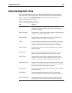

If the qualifier
is . . . Then . . .
7 testing occurs at power-up initialization. Communications
between the microstepper controller and the CPB are
monitored for the response time to a command from the
microstepper controller. The test steps are:
S Reset the microstepper controller.
S Enable microstepper controller.
S Wait 100 µS for a response from the controller. If no
response, the controller is not operating correctly.
8 testing is performed on a clean, sample chamber filled with
bubble-free 7.3 Buffer/CO-ox Zero solution. During
subsequent zeros the integration time is checked and
readjusted (zero occurs during any 1-point calibration, except
metabolite). If necessary, the lamp voltage or intensity is
adjusted. Full calibration occurs during system initialization at
start up. Testing also occurs during every sample, slope, or
zero measurement.
9 testing occurs at power-up initialization by reading +12V and
–12V with the general purpose ADC. The ±12V values are
scaled to ±3.0V before going into the ADC. The ADC
reading is to be +3.0V ±3% and –3.0V ±3%, respectively.
10 testing occurs at start up and during the CO-ox pump MIT
(Pump MIT selects CO-ox). This test checks for current flow
through the windings. A failure indicates that the motor driver
electronics are malfunctioning or that the motor is
disconnected. A MTR_CLR signal is initiated prior to reading
the MTR_STATUS bit, which clears the latch from prior
motor function. A TTL 1 on the MTR_STATUS identifies
current flow through the motor windings.
11 testing occurs each time the general purpose ADC is
calibrated. The GPADC is calibrated at power-up
initialization, and each zero and slope calibration. Setting the
GPADC to signal return and averaging several A/D readings
determines Offset. Offset is checked to be within the range 0
±100 mV. Setting the channel to the DAC reference signal
and averaging several A/D readings determines Gain. Gain is
computed as 5000 mV /(gain – offset reading). The value of
Gain is 1.00 ±0.01.
12
testing occurs at start up. This test checks the status of the
24V power supply by measuring the 24V supply with the
general purpose ADC. The 24V feed to the ADC is scaled
down to 3.0V. The ADC reading is to be 3.0V ±10%.