


Installation HĆ17
Installing the 800 COĆox Module to the 800 Base Model
This procedure refers to right and left as you are looking at the rear of system.
NOTE: Placing a piece of paper under the CO-ox module will allow for easier
movement on the work surface.
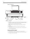
1. Move the CO-ox module close to the right side of the 800 base model.
2. Ensure that the CO-ox module hydraulic wall is open and slide the hydraulic
wall into position.
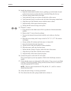
3. Install the CO-ox power cable:
a. Insert the CO-ox module power cable through the access hole in the side of
the 800 base model.
b. Gently pull the cable through the access hole while pushing the CO-ox
module as close to the 800 base model as possible.
c. Connect the CO-ox module power cable to J38 on the 800 base model
Backplane board.
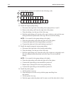
4. Install the side panel from the base model to the CO-ox module.
5. Close the 800 base model, but do not tighten the locking screws.
6. Lift the side of the 800 base model up slightly to ensure that the lip of the
CO-ox module is seated in the groove located under the chassis shelf of the
800 base model.
Ensure that the two bosses on the CO-ox module are seated in the two
receptacles of the base model and that the screws are aligned with the bosses.
Do not tighten the screws.
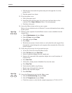
7. Move the CO-ox module hydraulic wall laterally along its hinge pin until the
sides of both units touch.
NOTE:ĄĂThe two alignment bosses on the left side of the CO-ox module
hydraulic wall must be seated properly in the hydraulic wall receptacles of the
800 base model.
CAUTION:ĄĂDo not crimp or pinch tubing between the hydraulic walls.
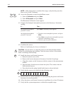
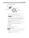
8. Secure the hydraulic walls together:
NOTE:ĄĂInstall the top rear screw first. You may need to remove the filter if it
prevents access to the top (upper rear) through hole. Be careful not to cut the
optics cable when securing the bottom (lower front) screw.
a. Ensure that the rear walls of both chassis are properly aligned.
b. Ensure that the captive screws are not engaged in the threaded portion of
the CO-ox hydraulic wall.
c. Insert a screwdriver into the access holes on the CO-ox module hydraulic
wall and tighten the screws to secure the hydraulic walls together.
!