


4Ć72
800 Series Operator's Manual
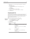
Testing a Sensor Circuit
Tools and Supplies
S TB1, pO
2
/pCO
2
Test/Blank Sensor
S TB2, pH/Na
+
Test/Blank Sensor
S TB3, K
+
/Ca
++
/Cl
–
Test/Blank Sensor
S TB4, Glucose/Lactate Test/Blank Sensor
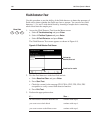
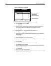
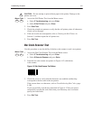
1. Access the Measurement Test from the Menu screen:
a. Select
3 Troubleshooting and press Enter.
b. Select 3 Measurement and press Enter.
CAUTION: Touch the inner surface of the module frame to discharge static
buildup before removing or returning sensors.
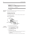
2. Remove the appropriate sensors:
a. Open the measurement module door.
b. If you are testing a pH or ISE sensor circuit, remove the reference sensor.
c. Remove the measurement sensor.
d. Close the measurement module door.
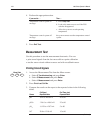
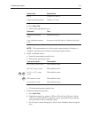
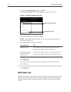
3. Perform the Measurement Test without a sensor:
a. Press
Start Test.
b. Take a reading of the actual sensor output signal.
c. Compare the result to the expected value.
NOTE:ĄĂTwo values are reported for the glucose and lactate biosensors.
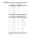
Sensor Circuit Expected Value
pCO
2
–6.000 to +6.000 mV
pO
2
20.607 to 16.191 nA
pH, Na
+
, K
+
, Ca
++
, or Cl
–
–6.000 to +6.000 mV
Glu I –5.348 to +5.348 nA
Glu A 25.252 to 54.748 nA
Lac I
–5.348 to +5.348 nA
(Continued)
3
Menu Code
3
!
860
860
860