


Installation HĆ5
Refer to the table below to identify the correct fuses for the voltage you use.
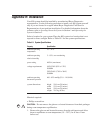
Voltage Fuse Rating Fuse Type
100/120V 4A Slo Blo 5 x 20 mm
220/240V 2A Slo Blo 5 x 20 mm
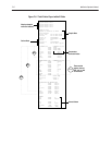
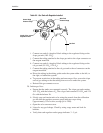
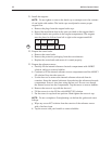
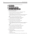
g. Install the fuses as shown in Figure H-3.
h. Slide the fuse holder(s) back into the fuse compartment. Make sure that the
arrow on the end of the holder points to your right, as indicated by the
arrows printed inside the compartment.
i. Close the fuse compartment door and make sure that the required
voltage is visible through the compartment window.
Do not connect the power cord to the AC wall outlet.
15. Insert the power cord into the power input connector on the right side panel.
16. Rotate the system so that the front panel faces you.
17. Adjust the Display assembly:
a. Remove the packing material from the hinges.
b. Lift the display assembly up.
18. Remove the front cover of the system.
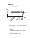
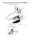
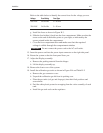
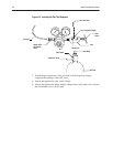
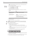
19. Install the calibration gas tanks as shown in Figure H-4 and Table H-2:
a. Remove the gas connector cover.
b. Unpack the calibration gas kit from its packing case.
c. Place the gas tanks (cal gas and slope gas) into their final positions and
secure them.
d. Peel the white plastic protective wrapping from the valve assembly of each
tank.
e. Install the gas tank seals on the regulators.
WARNING