


Installation HĆ7
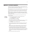
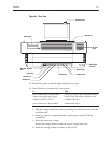
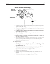
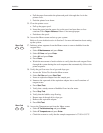
Second Stage
Pressure Gauge
Main Tank
Pressure Gauge
Needle Valve
Adjustment Knob
Gas Tank
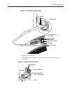
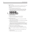
i. Connect one end of a length of black tubing to the regulator fitting on the
slope gas tank (10% CO
2
).
j. Connect the tubing attached to the slope gas tank to the slope connector on
the reagent manifold.
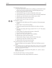
k. Connect one end of a length of black tubing to the regulator fitting on the
cal gas tank (5% CO
2
, 12% O
2
).
l. Connect the tubing attached to the cal gas tank to the cal connector on the
reagent manifold.
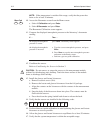
m. Direct the tubing in the tubing guide under the system either to the left, to
the right, or behind the system.
n. To prevent restrictions in the tubing and uneven gas flow, secure the slope
and cal gas tubing so that the tubing does not cross under the system.
o. Reinstall the gas connector cover.
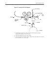
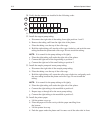
20. Initiate gas flow:
a. Ensure that the tanks are connected correctly. The slope gas tank contains
10% CO
2
with the balance N
2
. The cal gas tank contains 5% CO
2
and 12%
O
2
with the balance N
2
.
b. Slowly open each main tank valve using the wrench from the calibration
gas kit until the regulator pressure gauge indicator stops rising
(approximately 3/4 of a turn; average psi is 2200).
c. Open the valve one more turn.
d. Listen for any gas leakage. Check by using soapy water and look for
bubbles.
e. Verify that each regulator outlet gauge indicates 3 – 5 psi.