8XC196NP, 80C196NU USER’S MANUAL
B-14
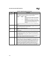
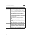
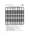
P4.3 — WK1 WK1 (Note 1) (Note 1) (Note 1) —
EPORT.3:0 A19:16 WK1 1 (Note 5) (Note 5) (Note 6) (Note 8)
— A15:0 WK1 LoZ0 (Note 7) (Note 7) HiZ LoZ0
— AD15:0 WK1 LoZ0 (Note 7) (Note 7) HiZ LoZ0
— ALE WK0 0 (Note 9) (Note 9) WK0 LoZ0
— BHE# WK1 1 (Note 10) (Note 10) WK1 LoZ1
— EA#
(NP only)
HiZ HiZ HiZ HiZ HiZ —
— INST WK0 0 (Note 9) (Note 9) WK0 LoZ0
— NMI WK0 WK0 WK0 WK0 WK0 —
— ONCE MD0 MD0 MD0 MD0 MD0 —
— PLLEN1
(NU only)
HiZ HiZ HiZ HiZ HiZ —
— PLLEN2
(NU only)
MD0 MD0 MD0 MD0 MD0 —
— RD# WK1 1 (Note 10) (Note 10) WK1 LoZ1
— READY WK1 WK1 WK1 WK1 WK1 —
— RESET# 0 WK1 WK1 WK1 WK1 —
— RPD LoZ1 LoZ1 LoZ1 LoZ1 LoZ1 —
— WR# WK1 1 (Note 10) (Note 10) WK1 LoZ1
XTAL1 —
Osc input,
HiZ
Osc input,
HiZ
Osc input,
HiZ
Osc input,
HiZ
Osc
input,
HiZ
—
XTAL2 — Osc output,
LoZ0/1
Osc output,
LoZ0/1
Osc
output,
LoZ0/1
HiZ Osc
output,
LoZ0/1
—
NOTE:
1. If P
x_
MODE.
y
= 0, then port is as programmed. If P
x_
MODE.
y
= 1, then as specified by the associ-
ated peripheral.
2. If P2_MODE.7 = 0, then port is as programmed. If P2_MODE.7 = 1, then 1.
3. Used as chip select: If HLDA# = 0, then WK1. If HLDA# = 1, then LoZ1. Used as port: then port is as
programmed.
4. Used as chip select: WK1. Used as port: then port is as programmed.
5. When used as extended address: If HLDA# = 1, then 0. If HLDA# = 0, then HiZ
When used as EPORT, then port value.
6. When used as extended address, then HiZ. When used as EPORT, then port value.
7. If HLDA# = 1, then LoZ0. If HLDA# = 0, then HiZ.
8. When used as extended address: then previous address. When used as EPORT: then port value.
9. If HLDA# = 1, then LoZ0. If HLDA# = 0, then WK0.
10. If HLDA# = 1, then LoZ1. If HLDA# = 0, then WK1.
11. The values in this column are valid until user code configures the specific signal (i.e., until P
x
_MODE
is written).
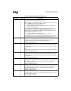
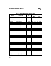
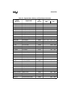
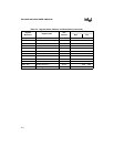
Table B-5. 8XC196NP and 80C196NU Pin Status (Continued)
Port Pins
Multiplexed
With
During
RESET#
Active
Upon
RESET#
Inactive
(Note 11)
Idle
Power-
down
(NP/NU)
and
Standby
(NU only)
Hold
Bus
Idle


