12-5
SPECIAL OPERATING MODES
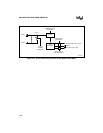
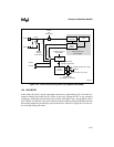
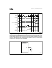
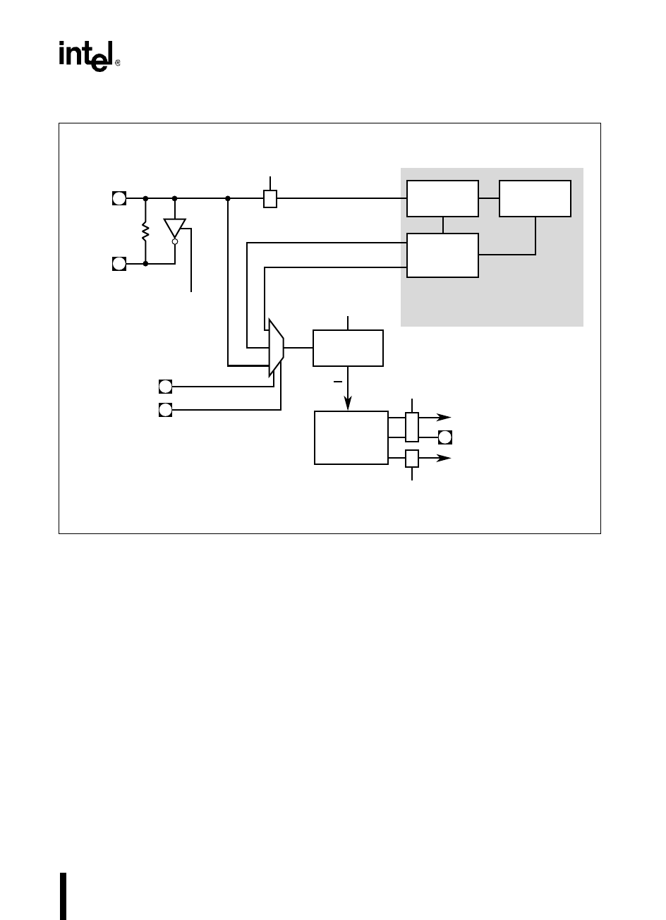
Figure 12-2. Clock Control During Power-saving Modes (80C196NU)
12.3 IDLE MODE
In idle mode, the device’s power consumption decreases to approximately 40% of normal con-
sumption. Internal logic holds the CPU clocks at logic zero, causing the CPU to stop executing
instructions. Neither the phased-locked loop circuitry (80C196NU only), the peripheral clocks,
nor CLKOUT are affected, so the special-function registers (SFRs) and register RAM retain their
data and the peripherals and interrupt system remain active. Table B-5 on page B-13 lists the val-
ues of the pins during idle mode.
A3063-02
Clock
Generators
CPU Clocks (PH1, PH2)
Divide-by-two
Circuit
PLLEN1
Phase-locked Loop
Clock Multiplier
Phase
Comparator
Filter
Phase-
locked
Oscillator
PLLEN2
Disable
PLL
(Powerdown)
Peripheral Clocks (PH1, PH2)
CLKOUT
Disable Clocks
(Standby, Powerdown)
Disable Clocks
(Idle, Standby, Powerdown)
XTAL1
XTAL2
F
XTAL1
Disable
Oscillator
(Powerdown)
Disable Clock Input
(Powerdown)
f
F
XTAL1
2F
XTAL1
4F
XTAL1
f
2


