8XC196NP, 80C196NU USER’S MANUAL
13-44
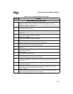
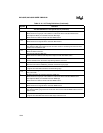
The 8XC196N
x
Meets These Specifications (Continued)
T
RHAX
(Multiplexed Mode) AD15:8/CS
x
# Hold after RD# High
Minimum time the high byte of the address in 8-bit mode will be valid after RD# inactive.
(Demultiplexed Mode) A19:0/CS
x
# Hold after RD# High
Minimum time the address will be valid after RD# inactive.
T
RHBX
BHE#, INST Hold after RD# High
Minimum time these signals will be valid after RD# inactive.
T
RHLH
RD# High to ALE Rising
Time between RD# going inactive and the next ALE. Useful in calculating time between RD#
inactive and next address valid.
T
RHRL
RD# High to RD# Low
Minimum RD# inactive time.
T
RHSH
A19:0/CS
x
# Hold after RD# High
Minimum time the address and chip-select output are held after RD# inactive.
T
RLAZ
RD# Low to Address Float
Used to calculate when the device stops driving address on the bus.
T
RLCH
RD# Low to CLKOUT High
Maximum time between RD# being asserted and CLKOUT going high.
T
RLCL
RD# Low to CLKOUT Low
Length of time from RD# asserted to CLKOUT falling edge.
T
RLRH
RD# Low to RD# High
RD# pulse width.
T
WHAX
(Multiplexed Mode) AD15:8/CS
x
# Hold after WR# High
Minimum time the high byte of the address in 8-bit mode will be valid after WR# inactive.
(Demultiplexed Mode) A19:0/CS
x
# Hold after WR# High
Minimum time the address will be valid after WR# inactive.
T
WHBX
BHE#, INST Hold after WR# High
Minimum time these signals will be valid after WR# inactive.
T
WHLH
WR# High to ALE High
Time between WR# going inactive and next ALE. Also used to calculate WR# inactive and next
Address valid.
T
WHQX
Data Hold after WR# High
Length of time after WR# rises that the data stays valid on the bus.
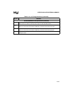
Table 13-16. AC Timing Definitions (Continued)
Symbol Definition


