8XC196NP, 80C196NU USER’S MANUAL
6-22
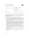
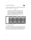
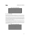
The PTSCB in Table 6-5 defines nine PTS cycles. Each cycle moves a single word from location
20H to an external memory location. The PTS transfers the first word to location 6000H. Then it
increments and updates the destination address and decrements the PTSCOUNT register; it does
not increment the source address. When the second cycle begins, the PTS moves a second word
from location 20H to location 6002H. When PTSCOUNT equals zero, the PTS will have filled
locations 6000–600FH, and an end-of-PTS interrupt is generated.
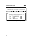
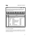
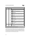
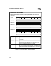
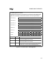
Register Location Function
PTSCON PTSCB + 1 PTS Control Bits
M2:0 PTS Mode
M2 M1 M0
1 0 0 single transfer mode
BW Byte/Word Transfer
0 = word transfer
1 = byte transfer
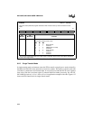
SU
†
Update PTSSRC
0 = reload original PTS source address after each byte or word
transfer
1 = retain current PTS source address after each byte or word
transfer
DU
†
Update PTSDST
0 = reload original PTS destination address after each byte or
word transfer
1 = retain current PTS destination address after each byte or
word transfer
SI
†
PTSSRC Autoincrement
0 = do not increment the contents of PTSSRC after each byte
or word transfer
1 = increment the contents of PTSSRC after each byte or word
transfer
DI
†
PTSDST Autoincrement
0 = do not increment the contents of PTSDST after each byte
or word transfer
1 = increment the contents of PTSDST after each byte or word
transfer
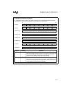
PTSCOUNT PTSCB + 0 Consecutive Word or Byte Transfers
Defines the number of words or bytes that will be transferred during the
single transfer routine. Each word or byte transfer is one PTS cycle.
Maximum value is 255.
†
The DU/DI bits and SU/SI bits are paired in single transfer mode. Each pair must be set or cleared
together. However, the two pairs, DU/DI and SU/SI, need not be equal.
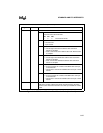
PTS Single Transfer Mode Control Block (Continued)
Figure 6-12. PTS Control Block — Single Transfer Mode (Continued)


