7-6
8XC196NP, 80C196NU USER’S MANUAL
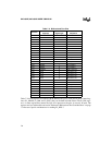
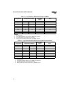
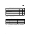
Table 7-4. Logic Table for Bidirectional Ports in I/O Mode
Configuration Complementary Output
Open-drain
Output
Input
P
x
_MODE 00 0 0
P
x
_DIR 00 1 1
SFDIR XX X X
SFDATA XX X X
P
x
_REG 0 1 0, 1 (Note 2) 1
Q1 off on off off
Q2 on off on, off (Note 2) off
P
x
_PIN 0 1 X (Note 3) high-impedance (Note 4)
NOTES:
1. X = Don’t care.
2. If P
x
_REG is cleared, Q2 is on; if P
x
_REG is set, Q2 is off.
3. P
x
_PIN contains the current value on the pin.
4. During reset and until the first write to P
x
_MODE, Q4 is on.
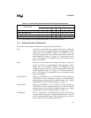
Table 7-5. Logic Table for Bidirectional Ports in Special-function Mode
Configuration Complementary Output
Open-drain
Output
Input
P
x
_MODE 11 1 1
P
x
_DIR 00 1 1
SFDIR 00 1 1
SFDATA 0 1 0, 1 (Note 2) 1
P
x
_REG XX X 1
Q1 off on off off
Q2 on off on, off (Note 2) off
P
x
_PIN 0 1 X (Note 3) high-impedance (Note 4)
NOTES:
1. X = Don’t care.
2. If P
x
_REG is cleared, Q2 is on; if P
x
_REG is set, Q2 is off.
3. P
x
_PIN contains the current value on the pin.
4. During reset and until the first write to P
x
_MODE, Q4 is on.


