2-3
ARCHITECTURAL OVERVIEW
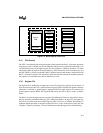
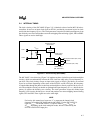
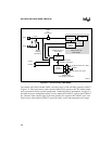
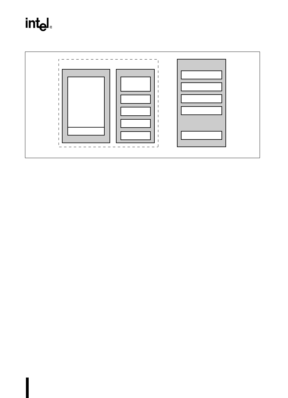
Figure 2-2. Block Diagram of the Core
2.3.1 CPU Control
The CPU is controlled by the microcode engine, which instructs the RALU to perform operations
using bytes, words, or double words from either the 256-byte lower register file or through a win-
dow that directly accesses the upper register file. (See Chapter 5, “Memory Partitions,” for more
information about the register file and windowing.) CPU instructions move from the 4-byte (for
the 8XC196NP) or 8-byte (for the 80C196NU) prefetch queue in the memory controller into the
RALU’s instruction register. The microcode engine decodes the instructions and then generates
the sequence of events that cause desired functions to occur.
2.3.2 Register File
The register file is divided into an upper and a lower file. In the lower register file, the lowest 24
bytes are allocated to the CPU’s special-function registers (SFRs) and the stack pointer, while the
remainder is available as general-purpose register RAM. The upper register file contains only
general-purpose register RAM. The register RAM can be accessed as bytes, words, or double-
words.
The RALU accesses the upper and lower register files differently. The lower register file is always
directly accessible with direct addressing (see “Addressing Modes” on page 4-6). The upper reg-
ister file is accessible with direct addressing only when windowing is enabled. Windowing is a
technique that maps blocks of the upper register file into a window in the lower register file. See
Chapter 5, “Memory Partitions,” for more information about the register file and windowing.
A2797-01
Register File
Register
RAM
CPU SFRs
RALU
Microcode
Engine
ALU
Master PC
Memory Controller
Prefetch Queue
Slave PC
Address Register
Data Register
CPU
Bus Controller
PSW
Registers


