7-13
I/O PORTS
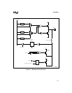
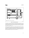
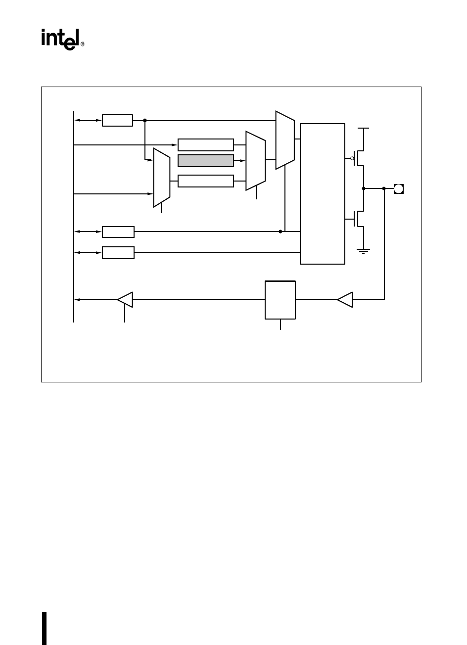
Figure 7-2. EPORT Block Diagram
If EP_MODE.x is set (address mode), the address multiplexer determines the address source. For
an instruction fetch, the address multiplexer is set to the CODE input, which selects the extended
program counter (EPC) as the address source. For a data fetch, or when there is no external bus
activity, the address multiplexer is set to the DATA input, which selects the extended data address
register (EDAR) as the address source.
The EDAR is loaded from two different sources, depending on whether the data access is extend-
ed or nonextended. For extended data accesses, the data multiplexer is set to the 1-Mbyte mode
input and EDAR is loaded with the extended address. For nonextended data accesses, the data
multiplexer is set to the 64-Kbyte mode input and EDAR is loaded from EP_REG. The last value
loaded remains in EDAR until the next data access. (Refer to “Fetching Code and Data in the 1-
Mbyte and 64-Kbyte Modes” on page 5-23 for more information.)
V
CC
Q2
Q1
Buffer
EP_REG
EP_DIR
Sample
Latch
PH1 Clock
Internal Bus
Extended Data Address
(from CPU)
EP_MODE
EP_PIN
DQ
LE
Combinational
Logic
Read Port
I/O Pin
Data/Address Control
(from Bus Controller)
I/O
(0)
ADR
(1)
CODE
EDAR
64K
1M
DATA
Data
Direction
EPC
MODE64 Control
(from CPU)
Extended Code Address
(from CPU)
I/O MUX
Address MUX
V
SS
Mode
A3113-01
NOTE: Shaded area is unique to the 80C196NU.
Force Page 00H


