9-1
CHAPTER 9
PULSE-WIDTH MODULATOR
The pulse-width modulator (PWM) module has three output pins, each of which can output a
PWM signal with a fixed frequency and a variable duty cycle. These outputs can be used to drive
motors that require an unfiltered PWM waveform for optimal efficiency, or they can be filtered
to produce a smooth analog signal.
This chapter provides a functional overview of the pulse-width modulator module, describes how
to program it, and provides sample circuitry for converting the PWM outputs to analog signals.
For detailed descriptions of the signals and registers discussed in this chapter, please refer to Ap-
pendix B, “Signal Descriptions” and Appendix C, “Registers.”
9.1 PWM FUNCTIONAL OVERVIEW
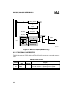
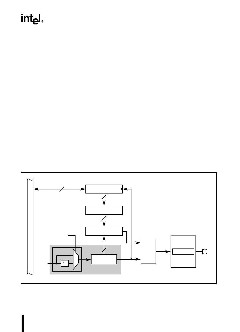
The PWM module has three channels, each of which consists of a control register
(PWMx_CONTROL, where x is 0, 1, or 2), a buffer, a comparator, an RS flip-flop, and an output
pin. Two other components, an eight-bit counter and a clock prescaler, are shared across the PWM
module’s three channels, completing the circuitry (see Figures 9-1 and 9-2).
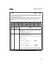
Figure 9-1. PWM Block Diagram (8XC196NP Only)
A2382-03
PWM
x
_CONTROL
R
S
Q
Port 4
Control
P4_MODE
P4.
x/
PWM
x
8
8
Buffer
x
8
Comparator
x
8
Up Counter
PWM
x
Output
Overflow
=
Load
Buffer
– 2
0
1
Prescaler
Internal
Clock
Signal
CON_REG0.0
(CLK0 Bit)
RS Flip-flop
x
Shared Circuitry


