8XC196NP, 80C196NU USER’S MANUAL
10-26
time_value = epa0_time; /* must read to prevent overrun */
}
void init_timer1()
{
t1control = COUNT_ENABLE
¦
COUNT_UP ¦
CLOCK_INTERNAL ¦
DIVIDE_BY_1;
}
void main(void)
{
unsigned int time_value;
/* Initialize the timers and interrupts before using the EPA */
init_timer1();
init_epa0();
enable(); /* Globally enable interrupts */
while(1); /* loop forever, wait for interrupts to occur */
}
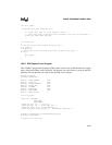
10.8.3 EPA PWM Output Program
This example C program demonstrates the generation of a PWM signal using the EPA’s PWM
toggle mode (see “PWM Modes” on page 6-26) and shows how to service the interrupts with the
PTS. The PWM signal in this example has a 50% duty cycle.
#pragma model(EX)
#include <80c196np.h>
#define PTS_BLOCK_BASE 0x98
/* Create typedef template for the PWM_TOGGLE mode control block.*/
typedef struct PWM_toggle_ptscb_t {
unsigned char unused;
unsigned char ptscon;
void *pts_ptr;
unsigned int constant1;
unsigned int constant2;
} PWM_toggle_ptscb;
/* This locates the PTS block mode control block in register ram. This */
/* control block may be located at any quad-word boundary. */
register PWM_toggle_ptscb PWM_toggle_CB_3;
#pragma locate(PWM_toggle_CB_3=PTS_BLOCK_BASE)
/* The PTS vector must contain the address of the PTS control block.*/
#pragma pts(PWM_toggle_CB_3=0x3)
/* Sample PTS control block initialization sequence.*/


