12-1
CHAPTER 12
SPECIAL OPERATING MODES
The 8XC196NP and 80C196NU provide the following power saving modes: idle, standby
(80C196NU only), and powerdown. They also provide an on-circuit emulation (ONCE) mode
that electrically isolates the device from the other system components. This chapter describes
each mode and explains how to enter and exit each. (Refer to Appendix A for descriptions of the
instructions discussed in this chapter, to Appendix B for descriptions of signal status during each
mode, and to Appendix C for details about the registers.)
12.1 SPECIAL OPERATING MODE SIGNALS AND REGISTERS
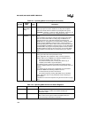
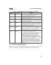
Table 12-1 lists the signals and Table 12-2 lists the registers that are mentioned in this chapter.
Table 12-1. Operating Mode Control Signals
Port Pin
Signal
Name
Type Description
P2.7 CLKOUT O Clock Output
Output of the internal clock generator. The CLKOUT frequency is ½
the internal operating frequency (f). CLKOUT has a 50% duty cycle.
CLKOUT is multiplexed with P2.7.
P3.7
P3.6
P2.4
P2.2
EXTINT3
EXTINT2
EXTINT1
EXTINT0
I External Interrupts
In normal operating mode, a rising edge on EXTINT
x
sets the
EXTINT
x
interrupt pending bit. EXTINT
x
is sampled during phase 2
(CLKOUT high). The minimum high time is one state time.
In standby and powerdown modes, asserting the EXTINT
x
signal for
at least 50 ns causes the device to resume normal operation. The
interrupt need not be enabled, but the pin must be configured as a
special-function input (see “Bidirectional Port Pin Configurations” on
page 7-7). If the EXTINT
x
interrupt is enabled, the CPU executes the
interrupt service routine. Otherwise, the CPU executes the instruction
that immediately follows the command that invoked the power-saving
mode.
In idle mode, asserting any enabled interrupt causes the device to
resume normal operation.
— ONCE I On-circuit Emulation
Holding ONCE high during the rising edge of RESET# places the
device into on-circuit emulation (ONCE) mode. This mode puts all
pins into a high-impedance state, thereby isolating the device from
other components in the system. The value of ONCE is latched when
the RESET# pin goes inactive. While the device is in ONCE mode,
you can debug the system using a clip-on emulator. To exit ONCE
mode, reset the device by pulling the RESET# signal low. To prevent
accidental entry into ONCE mode, connect the ONCE pin to V
SS
.


