11-9
MINIMUM HARDWARE CONSIDERATIONS
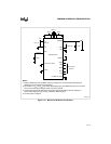
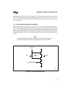
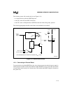
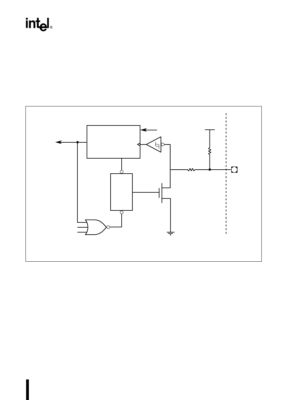
The following events will reset the device (see Figure 11-8):
• an external device pulls the RESET# pin low
• the CPU issues the reset (RST) instruction
• the CPU issues an idle/powerdown (IDLPD) instruction with an illegal key operand
The following paragraphs describe each of these reset methods in more detail.
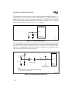
Figure 11-8. Internal Reset Circuitry
11.6.1 Generating an External Reset
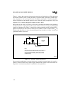
To reset the device, hold the RESET# pin low for at least one state time after the power supply is
within tolerance and the oscillator has stabilized. When RESET# is first asserted, the device turns
on a pull-down transistor (Q1) for 16 state times. This enables the RESET# signal to function as
the system reset.
A2416-01
Internal
Reset
Signal
Reset State
Machine
Trigger
Clock
Internal
External
R
RST
†
CLR
Q
RST Instruction
RESET#
~200 Ω
Stop
Q1
SET
IDLPD Invalid Key
V
CC
† See the datasheet for minimum and maximum R
RST
values.


