7-16
8XC196NP, 80C196NU USER’S MANUAL
7.3.1.5 Input Mode
Input mode is obtained by configuring the pin as an open-drain output (EP_DIR set and
EP_MODE clear) and writing a one to EP_REG.x. In this configuration, Q1 and Q2 are both off,
allowing an external device to drive the pin. To determine the value of the I/O pin, read EP_PIN.x.
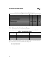
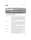
Table 7-11 is a logic table for I/O operation and Table 7-12 is a logic table for address mode op-
eration of EPORT.
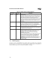
Table 7-11. Logic Table for EPORT in I/O Mode
Configuration Complementary Output
Open-drain
Output
Input
EP_MODE 00 0 0
EP_DIR 0 0 0, 1 (Note 2) 1
EP_REG 01 0 1
Address Bit XX X X
Q1 off on off off
Q2 on off on off
EP_PIN 0 1 0 high-impedance
NOTES:
1. X = Don’t care.
2. If EP_REG is clear, Q2 is on; if EP_REG is set, Q2 is off.
Table 7-12. Logic Table for EPORT in Address Mode
Configuration Complementary Output (Note 1)
EP_MODE 11
EP_DIR XX
EP_REG X (Note 2) X (Note 2)
Address Bit 01
Q1 off on
Q2 on off
EP_PIN 01
NOTES:
1. X = Don’t care.
2. EP_REG is output on EPORT during any nonextended external memory access.


